www.dtec.net.au
Chapter 16: Load Controllers
Expansion port functions
Throttle Output: The throttle can be controlled via a conventional servo if required, this is a feature usually reserved for
engine dyno applications.
The load controller outputs conventional ‘servo pulse code’ (1000-2000us) that is supported by most heavy duty servos.
*NOTE: Servos are very sensitive to electrical interference. The DTec breakout board has a small filter capacitor
added, but generally you will need to place a small capacitor (e.g. 0.1 uF) between across the signal to ground
and also the signal to power supply wire directly at the servo.
In high interference environments such as with CDI ignition it is better to make the throttle ‘pull cable’ out of a
nonconductive material (nylon line) and mount the servo at a distance.
Slowing down the Throttle servo speed may help to reduce the effects of interference if on the input lines.
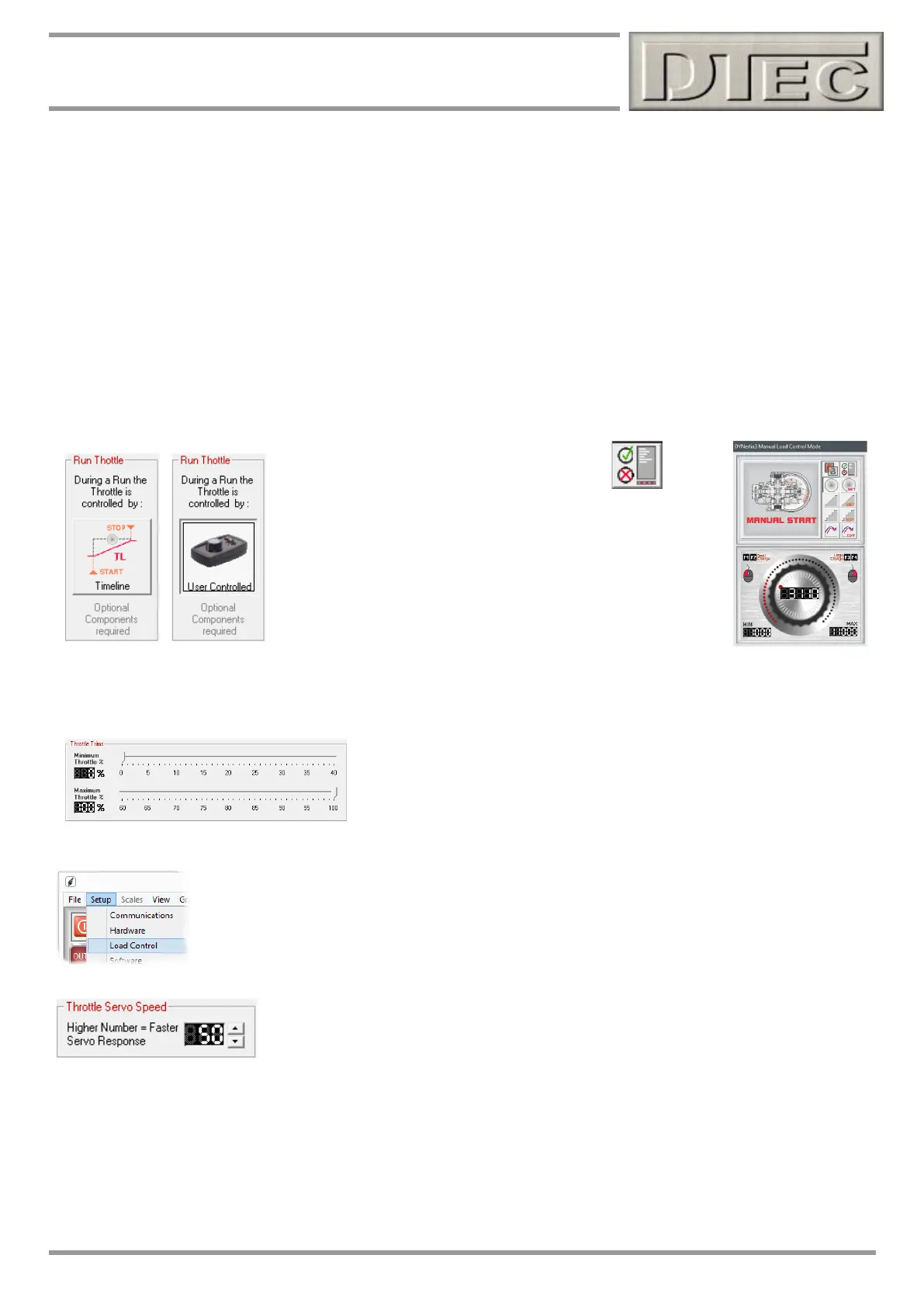
From within the ‘Run Options, Files and Information’ window (opened from the Load control window)-
The servo throttle can be configured to adopt it’s settings from the ‘Timeline’ or to be manually controlled via a
potentiometer input.
The travel of the throttle servo can be controlled here. This should be set to
limit mechanical damage from over travel.
From within the menu ‘Setup’ open the ‘Load Control’ menu-
This setting controls response speed of a throttle servo if connected.
Tip- Too fast and the operation can be ‘jerky’.
Throttle Input: The throttle analogue input (0-5V) is usually derived from a potentiometer (variable resistor). The typical
value is between 5 KΩ to 10 KΩ. This is used to set the throttle position servo manually.
The 5V supply on terminal 8 of the expansion port can be used as the potentiometer reference supply voltage.
Tip- The potentiometer can take the form of a ‘dial’ (knob) but you can also configure a lever arrangement as tis may
be easier to operate.