www.dtec.net.au
Chapter 5: RPM Input Options
Summary of your RPM options
Your options (previously detailed) depend on the dyno design-
Engine dyno, dyno flywheel/brake coupled directly to the engine (1 flywheel rotation = 1 engine rotation)
# Option 2 is best.
No setting required, instead select “Shaft RPM” in the ‘Record Settings’ panel for “Current Ratio”.
Engine dyno, dyno flywheel/brake driven via gearing (1 flywheel rotation = x engine rotations)
# Option 3,4,6,7 can be used. Option 4 is very easy and very accurate (assuming clutch is engaged).
Set “User Ratio” based on the gearing (eg. Number of dyno flywheel driven gear teeth divided by number of teeth on
engine drive gear). Select “User” in the ‘Record Settings’ panel for “Current Ratio”.
If ratio unknown and the engine has a tacho or you have an ‘RPM Adapter’ input connected then another option is to
simply use the ‘teaching’ options 3 or 6.
Chassis dyno (1 roller rotation = x engine rotations)
# Option 1,3,4,5,6,7 can be used. Option 1 is easiest (no RPM scale though), 3 is fast (but assumes constant test gear).
DYNertia3 can be ‘taught’ the relationship (ratio) of dyno roller to engine, up to 8 gears can be learnt and later selected
in the ‘Record Settings’ panel for “Current Ratio”, allows for very quick testing of the vehicle in any gear.
Enter an appropriate RPM as “Engine Target RPM”, choose a test gear, hold the engine RPM at the RPM number you
entered and when steady press the ‘Compute Ratio’ button of choice.
If you have the ‘RPM adapter’ input connected then DYNertia3 can read RPM from the engine directly or be ‘taught’ a
drive ratio to relate engine RPM to dyno RPM (RPM at the dyno’s sensor location). For this make sure you choose
correct settings in the “Setup/Hardware” menu. Press a ‘Compute Ratio’ of your choice and the ratio will be calculated
regardless of current engine RPM i.e. there is no need to set any RPM to hold the engine at! Just hold the engine RPM
relatively steady at any RPM for good results.
General RPM input information
It is important to understand that DYNertia3 can calculate engine RPM for its operations from it’s included sensor. If the
vehicle has gears and you are testing in a different gear to the selected ratio then the tacho will read incorrectly!
If you don’t set a ratio i.e. let the RPM used be roller RPM (select ‘roller RPM’ in ‘Record Settings’ panel). This will result
in the Torque figure being ‘tractive effort’ (at the wheels) and not engine torque. This can be very interesting as it’s the
actual power getting to the ground (for given dyno design) !
Note: ‘Slip’ calculations can’t operate with engines fitted with CVT transmissions or automatics that can’t be locked into
a set gear for testing, this is due to them having a continually changing drive ratio between engine and dyno flywheel.
The change in engine RPM vs dyno flywheel RPM would be shown as slip, even though this is not the case (may be of
interest anyway for development).
Note: Ramp testing on Brake type chassis dyno is best done using speed/sec and not RPM/sec, this is due to the
system needing a drive ratio to be set and maintained. Gear shifts or torque convertor slip will render it inaccurate due to
the fact that the dyno control system is controlling the roller RPM (a precision closed control loop) i.e. engine RPM must
be converted to roller RPM by the software to set the ramp rate, it can’t do this if the drive ratio changes.
Tip- If you know you’ll only be testing in one gear then only bother teaching that particular gear.
Tip- You can even name your ‘taught’ ratios for easy selection e.g. you may often test engine types with different
sprocket sizes, just pre-set the ratios and name after the engine type etc.
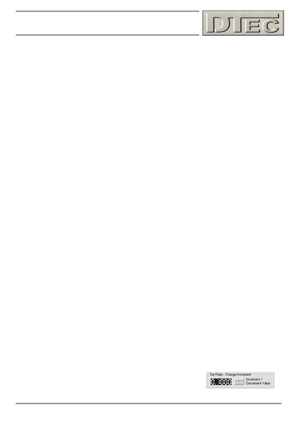
Tip- The small arrows next to the ratio buttons allow ‘nudging’ the value for fine
tunning if matching DYNertia3 RPM to vehicles tacho etc. (“Setup/Software” sets
step)