www.dtec.net.au
Chapter 3: ‘Brake’ Style Dyno Setup
Brake (Absorber) Style Dyno Setup
Basic concept
Brake (or absorber) style dyno’s rely on a device to apply load to the engine. In a chassis dyno, this device absorbing
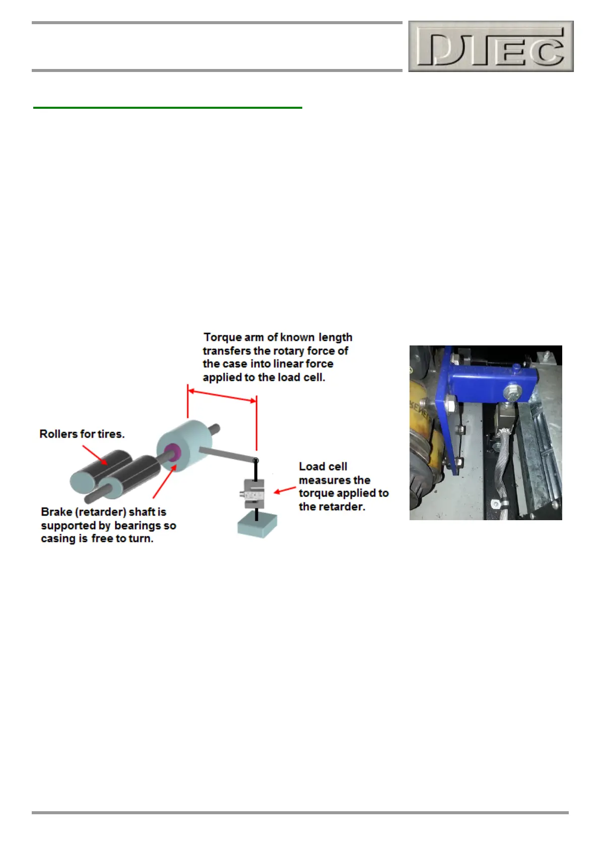
the power (we will use the term 'brake' or 'retarder') is generally mounted on the end of the rollers shaft so its case could
rotate as a load is applied if unrestrained. It is this rotational force that is measured to calculate the torque. Engine dyno
have the brake either directly mounted to the engine or via a reduction drive (Eddy retarders have a limited max RPM)
The case is attached to a load cell sensor via a ‘torque arm’ that transfers the rotary motion into the linear one applied to
the sensor.
The length of the arm acts as a lever, so this can be designed to suit the measuring range of your load cell and give
appropriate sensitivity (or even made with several load cell attachment points for variability).
Note: We use the term "load cell" here for our 'torque sensor', but this can be an alternative style such as a hydraulic
master cylinder and pressure sensor or even a mechanical spring and coil type 'potentiometer'.
Note: Please see the chapter on ‘Load Controller’ for the load cell wiring and calibration procedures.
If we know the force (in Nm allowing for the length of 'torque arm') applied to the load cell and the RPM of the shaft we
can calculate power by the metric formula Kw = (Nm x RPM) / 9549, this will be power at the wheels. By using a chassis
dyno we can have a very convenient and quick way of testing modifications, unfortunately the effect of drivetrain losses
and tire losses do have an impact, an engine dyno avoids many of these ‘losses’.
See www.DTec.net.au website ‘downloads’ for information (‘Brake Chassis Design Tool’ or ‘Brake Engine Design Tool’)
The DYNertia3 controller senses the speed of the brakes rotating shaft and outputs this data, along with the load cell
information to the PC for analysis and storage.
DYNertia3 software package handles all the functions required of dyno acquisition: setting up, saving runs, correcting for
atmospheric conditions, filtering, displaying data, printing, overlaying and analyzing multiple runs.