www.dtec.net.au
Chapter 16: Load Controllers
Load Cell Setup & Calibration
Calibration is performed by noting the voltage from the load cell at rest (this is zero Nm) and then apply a known weight
to the Torque arm so that this represents the Torque level you wish to measure
This also involves setting up the load cell amplifier so that the voltage output range is also effectively used. A guided
menu process can be used as outlined below. Manual entry of the data can be also made by recording it in the ‘Sensor
Configuration’ and entering the data in Nm at 0mV and 5000mV (see next section for details if required).
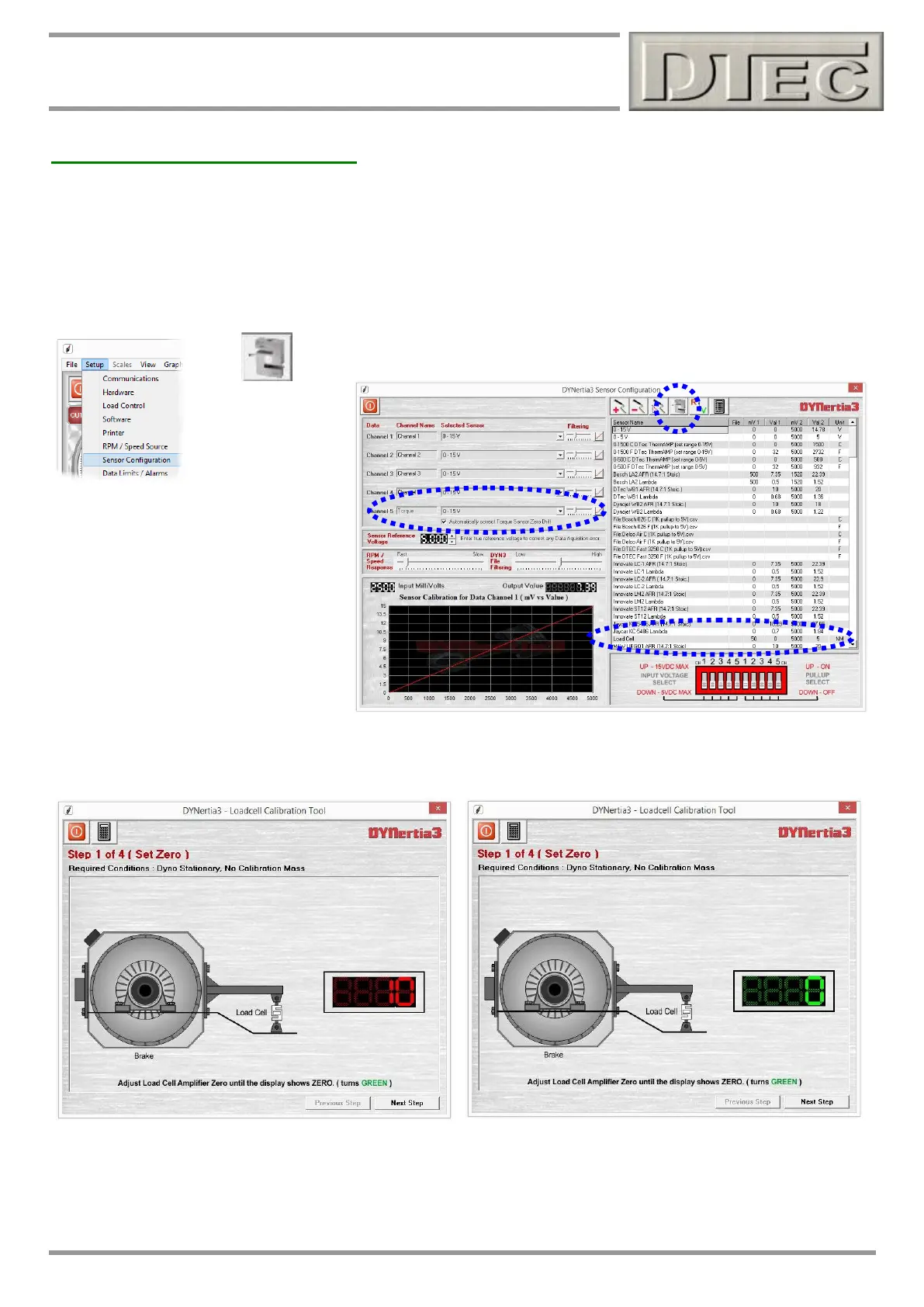
Sensor Calibration
Within the menu ‘Setup/Sensor Configuration’ is this button (load cell icon) that
opens the sensor calibration screens shown.
Note: This guided calibration procedure
allows for automatic ‘zeroing’ of the load
cell during use (it leaves a small 100mV
offset voltage so DYNertia3 software can
read a negative load if required). If you
wish you can turn off, deselect
“Automatically correct torque sensor for
zero torque drift” in menu ‘setup’/’sensor
configuration’
Note: The slider next to channel 5 will adjust the filtering to the load cell and affects the smoothness of your graph!
Step 1: explains setting the load cell amplifier so that it reads zero with no load (actually a small 100mV offset is
automatically set with this guided calibration sequence)
Adjust the amplifiers ‘Offset’ (zero or null) until the digits turn green as shown on the Right then press ‘Next Step’ button.
NOTE: If the ‘offset’ screw on DTec load cell amplifier is turned out too far anti-clockwise (lowering voltage) then the
output will suddenly go to a high voltage i.e. attempting to adjust lower will just force output Hi. See Amplifier datasheet
for information about fitting a resistance in series to lower the output further if required.