www.dtec.net.au
Chapter 2: Hardware Installation
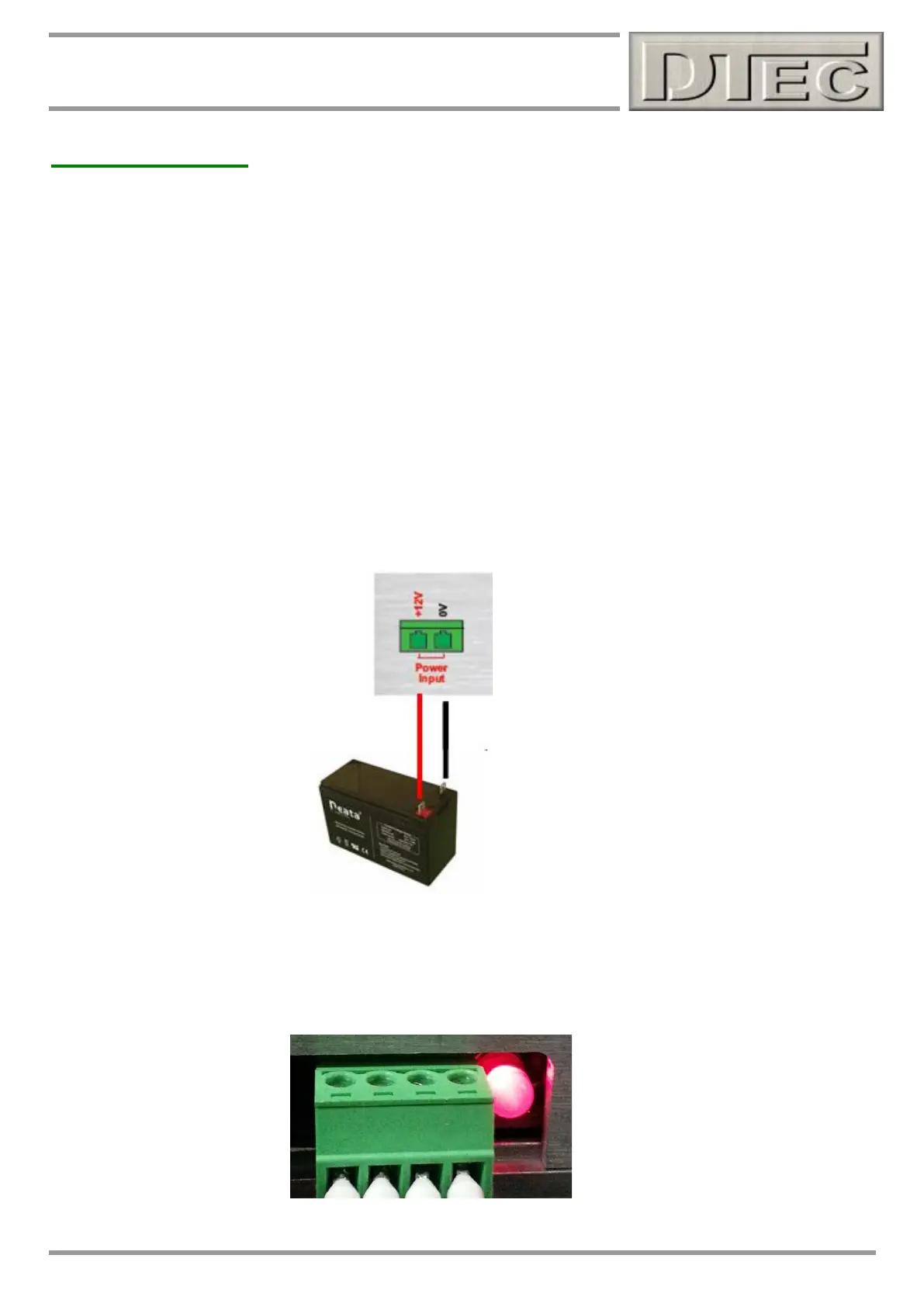
Hardware Wiring
Power supply connection
Please see chapter called ‘Inputs- Using’ of this manual for full wiring details on connection of data acquisition devices,
below we just cover the power supply connection required for basic operation.
Power supply can be from a simple 12VDC battery, 7 to 18VDC required. DYNertia3 typically draws less than 50mA so
very little demand is put on a battery e.g. a cordless drill or bike battery is ideal!.
A power pack connected to mains is NOT recommended, especially if data acquisition is being used. The resistance to
interference and stability of the data acquisition signals is generally much better with a battery! This is very dependant
on the dyno installation, PC used and engine types being tested (as to how much interference they produce). If using a
power supply it should be fully regulated (not just a battery charger!) and be trailed to ensure it is acceptable.
Full isolation protection (optical) for the PC is only provided when DYNertia3 is powered from a battery source.
NOTE: Very low battery voltage (less than 7VDC) will cause poor sensor operation and erratic results. Please monitor!
With power connected to DYNertia3 the status LED (next to the sensor connector) will blink twice at first to indicate
microprocessor is initialising. After this the LED will illuminate to indicate power, but don’t assume there is not a power
supply problem based solely on LED operation, it takes very little voltage to light an LED!