www.dtec.net.au
Chapter 6: Overview- 2 Main Windows
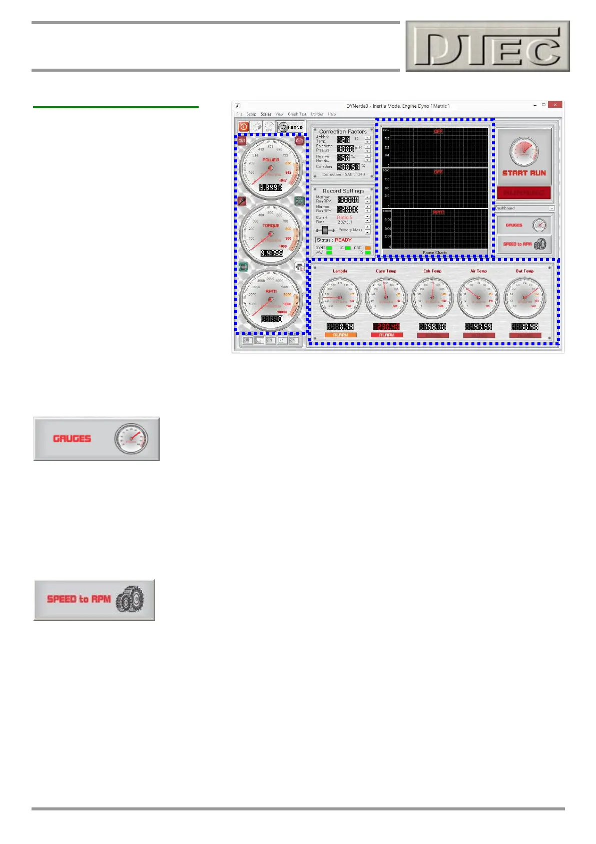
DYNO Window (cont.)
Dial Gauge Displays
Left hand dials are active for viewing
when the “Gauges” or “Speed to RPM”
button is pressed, also during a ‘Run’.
The range of the gauges is set in the
‘Scales’ menu or by clicking on the dials.
Power & Torque dials:
Note: Power and Torque gauges only
operate if dyno is a ‘brake’ type dyno, as
setup in “Setup/Hardware”.
RPM/Speed dial: Dials display either
RPM or speed depending on the
operating mode set by the ‘mode’ button
(icon of a ‘gauge’, Top Left of active
screen).
Tip- The RPM dials source will depend on the settings in “Setup/Hardware” regarding the ‘RPM Adapter’ input, see
“RPM Input options” chapter of manual for full details.
Gauges Mode
Data Gauges ON Button: Reveals the data acquisition dials, strip charts (shown above)
and enables the dial displays to display live information (i.e. not just to be used for
analysing graph traces).
This function is used for ‘steady state’ tunning when using a load cell, monitoring engines whilst testing or for setting up
an engine to confirm that DYNertia3 is receiving accurate data and that all settings are correct, especially the gear ratio
settings (i.e. that the ratio of dyno speed to engine speed is correct and RPM/speed reads correct). This mode can also
be used to calibrate vehicle speedometers.
Note: Rotation of the flywheel is required for these dials/charts to display data! To view data without rotation use the
menu choice ‘Utilities/Data Diagnostics’ instead.
Speed to RPM (ratio setting)
This button reveals a window used to quickly set gear ratios if required for RPM input setup.
Refer to the chapter “RPM Input Options”
Strip Charts: Scales come from the settings in the menu option ‘Scales’ and charts can be paused by pressing the
button ‘Pause Charts’ at the bottom.
Note: The RPM/speed chart is active whenever the ‘Gauges’ button is active but the Power and Torque charts (like their
corresponding dial gauges) only operate if dyno is setup as a ‘brake’ style dyno in ‘Setup/Hardware’.
Data Dial Gauges: All 5 data channels are displayed, but channel 5 is unavailable if the dyno is set as a ‘brake’ style
dyno in ‘Setup/Hardware’, as in this mode the load cell must be connected to this channel!
Names displayed above the dials come from the channel names in menu option ‘Setup/Sensor Configuration’ and scales
are also obtained from these menu settings.
Every gauge has a programmable alarm feature that can be set under menu “Setup/Data Limits Alarms”. When triggered
the ‘ALARM’ lamp display turns red or orange.