www.dtec.net.au
Chapter 16: Load Controllers
Expansion port functions (cont.)
Auxiliary Outputs 1 and 2: Thea Auxiliary outputs are an ‘active hi’ with 30mA max current allowed, they are designed
for solid state relays only (i.e. electronic relays that draw very little current unlike a conventional ‘coil’ style relay)
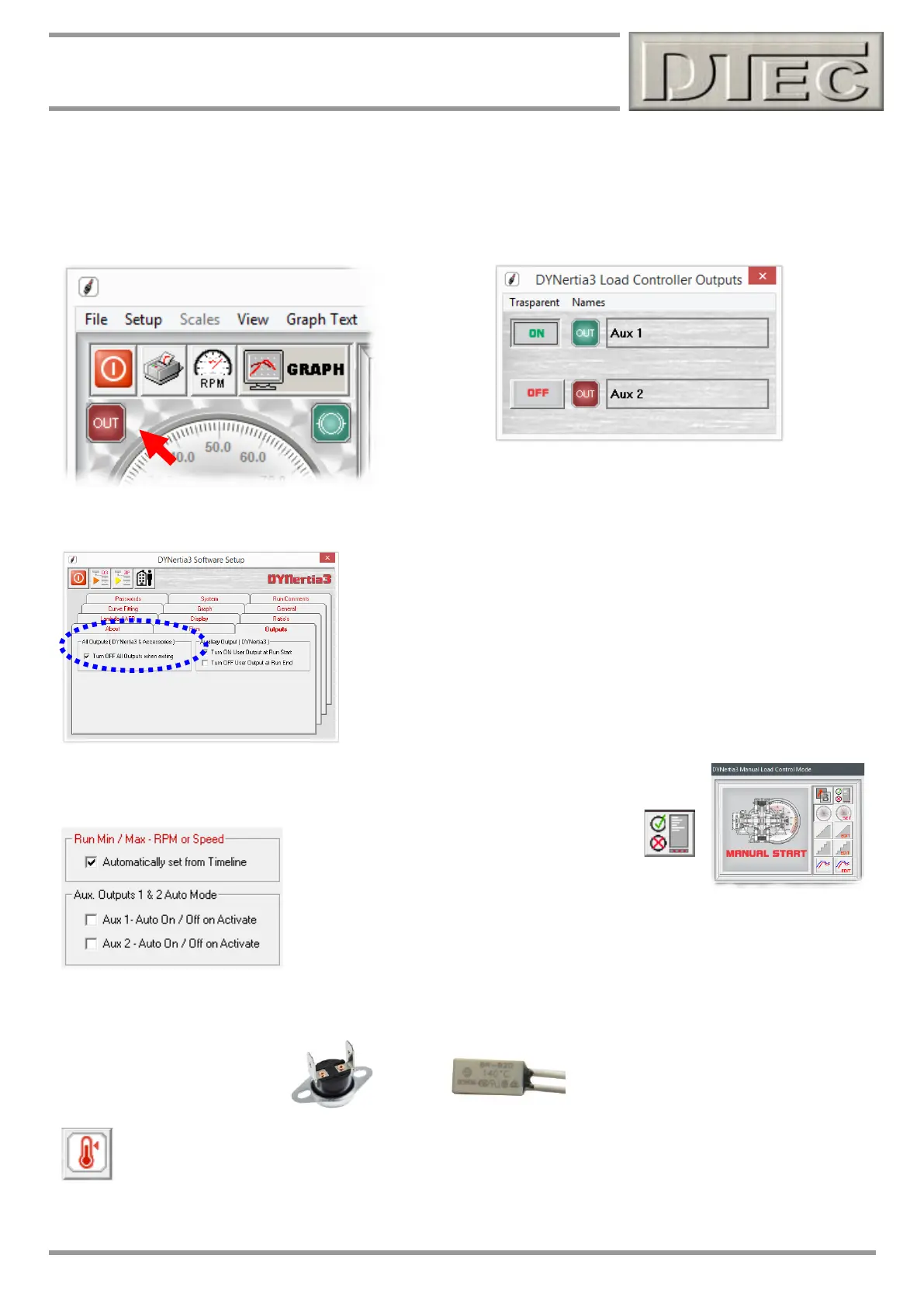
‘Right’ click on the icon (visible on both GRAPH and DYNO screen) will allow the manual control of both auxiliary outputs.
Note: This control window is not visible without the load controller
connected and ‘linked’.
From within the menu ‘Setup/Software/Outputs’-
You can set all outputs to be off upon software exiting. This ensures devices
connected to the auxiliary output terminals can be left in a suitable state
upon exiting the software.
From within the ‘Run Options, Files and Information’ window (opened from the Load control
window)-
Auxiliary outputs can be enabled to operate automatically during a test. Leave un-
checked for normal manual control.
Over Temperature Alarm Input: Load controller has the ability to have an over temperature alarm fitted to the retarder
so that a software triggered warning can be imposed. This must be a temperature sensor of the switch type and be
normally closed to ground.
From within the menu option ‘Setup/load control’ is the control button to activate the feature.