www.dtec.net.au
Chapter 2: Hardware Installation
Hardware Mounting
Mounting the DYNertia3 Sensor and Magnet
NOTE: When DYNertia3 is used with the optional ‘Load Controller’ (for ‘closed loop’ dyno) the sensor type and
mounting procedure shown below is not relevant, please see the ‘Load controller’ chapter for details.
DYNertia3 times the rotational period of a component by sensing its position magnetically. The included sensors ‘face’
contains a magnet sensing ‘Hall Effect’ switch. The sensor detects the position of the magnet attached to the rotating
dyno flywheel/load brake/shaft and processes to trigger the timing procedure.
NOTE: The rotation sensor system is the main RPM input used by DYNertia3 for Power calculation and therefore must
always be setup for operation. If you choose to also use the engine ignition system (or other source) as a secondary
RPM input then please read the chapter on ‘RPM Input Options’ in this manual regarding this optional input!
A small (9mm x 1.5mm with 3mm mounting hole) but very powerful ‘rare earth’ magnet is included with the kit. The
magnet is small as this reduces the forces involved when rotating so it is easier to secure safely.
Do not mount the magnet at the perimeter of the dyno flywheel/shaft/sprocket etc. as the centrifugal forces will be
highest; choose a location towards the centre area. The magnet is also very fragile and must be handled with care!
NOTE: The included sensor will only detect the ‘South’ Pole of a magnet, so the magnet must be have the South Pole
(marked with red paint) facing the sensor!!
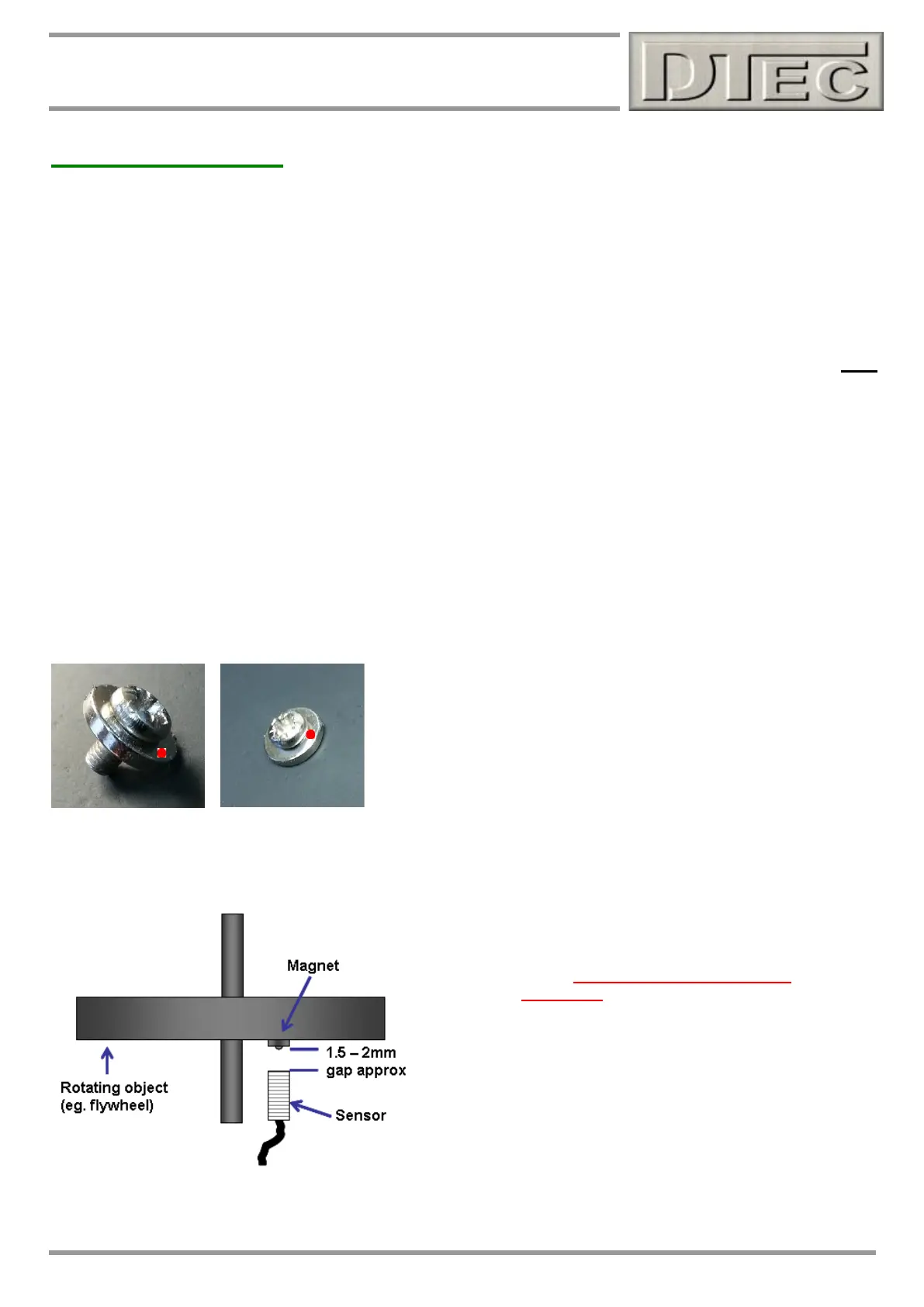
Mounting by screwing/gluing flat to dyno flywheel-
Dyno flywheel is drilled and tapped for 3mm screw (2.5mm drill size is
usual for 3mm tapping). Short (min 6mm) screw inserted into magnet.
Do not over tighten or magnet may crack!
Magnet epoxy glued and screwed to dyno flywheel with South Pole outwards.
The sensor face must be positioned 1.5 - 2mm from the
magnets South Pole (or the head of the screw if one is used
to secure magnet).