www.dtec.net.au
Chapter 14: Inputs- Using
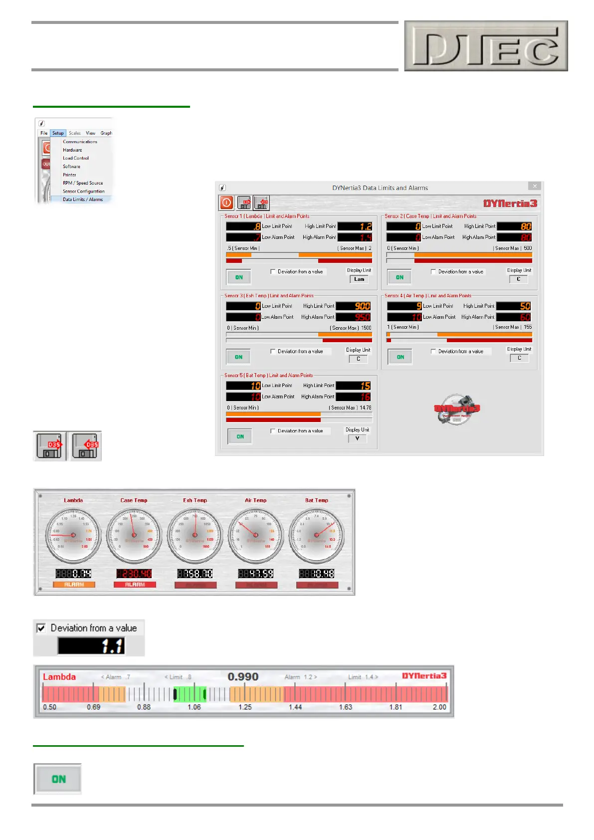
Sensor Alarm Points
Input sensors can have alarm and limit conditions attached that will turn the warning lamps either
red or orange upon triggering. This can be used for detecting damaging conditions like overheating
or even used to signify when conditions are acceptable for repeatable testing i.e. when engine
temperature is within a certain range.
Note: When viewing the data via
‘Data Channels’ Window the alarms
only apply if ‘unprocessed mV’ is not
selected to be displayed.
The alarm lamps appear on most
display screen during testing and
monitoring.
Settings also apply when viewing via
the monitoring dials on the main Dyno
screen (‘Gauges’ button is selected or
performing a run).
As shown below, the alarm lamps will
be either orange or red depending on if
the input exceeds a ‘limit’ or a full
‘alarm’ value.
Settings can be
optionally saved or
loaded from file.
This may be useful if you have made settings for particular engine types you frequently test.
The Alarm lamps here are shown in all 3
states-
Lambda has exceeded ‘limit’ value.
Case Temp has exceeded alarm value.
Other data is within range.
Setting a deviation value changes the way the bar graphs display in the “Tunning Gauges”
screen (only visible with dual monitors configured). It places a marker at the value entered
and the band shows the value as it moves either side of the marker, as oppose to the band
starting from the Left hand side.
Sensor On / Off (Recording)
This option in ‘Sensor Configuration’ allows the data acquisition channels to be easily turned on or off so as
they do not record when testing.