www.dtec.net.au
Chapter 16: Load Controllers
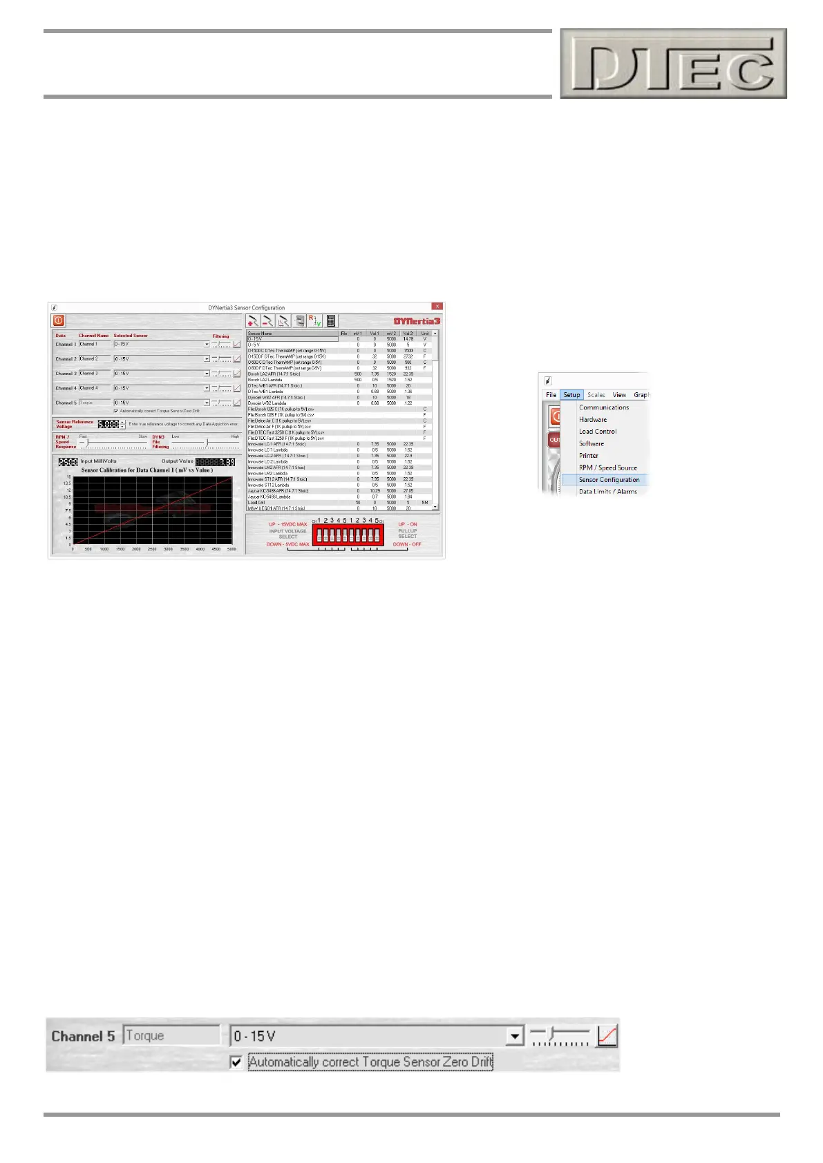
Manual Sensor Calibration
If you have an alternative torque sensor to a load cell or you otherwise just wish to perform a non-guided calibration then
it is possible to manually enter the sensor calibration data, just as you would for any other sensors.
Note: See chapter “Inputs- Using” for details on this process. Make sure the sensor is allocated to Channel 5 as this is
the only torque input used.
Calibrating your system adjusting (amplifier ‘Offset’ {zero or null}) so that 0Nm is 100mV will allow the ‘Automatic Sensor
Drift Cancellation’ mentioned below to still operate, even though a ‘guided’ calibration procedure was not used.
If not using the automatic drift cancellation then you can ignore setting up for a 100mV offset.
Note: The sensor input in DYNertia3 must be calibrated in metric Newton meters (Nm).
Calibration is performed by noting the voltage from the load cell at rest (this is zero Nm) and then apply a known weight
to the load cell so that this represents the torque level you wish to measure (you can add an extension to the arm so less
weight is needed if required during this calibration) . Take the voltage reading from the sensor when the weight is
applied and enter this into the sensor calibration table along with the calculated torque (as below).
Torque = load (weight in Kg applied x 9.80665) x length of torque arm in meter’s
Therefore, if I had 0.5 meter arm (centre of dyno bearing to arms end above load cell) and apply 30kg onto the load cell I
am applying a torque of 30 x 9.80665 x 0.5 = 147.1 Nm at the shaft.
So, if I had 10mV at no load (0 Nm) and 2000mV (2V) with my calibration weight applied (147.1 Nm) then these are my
two calibration points I need-
mV1=10, Val1= 0 and mV2=2000, Val2=147.1
Automatic Sensor Drift Cancellation
To allow automatic drift cancellation the guided calibration process leaves a small offset voltage at 0Nm (approximately
100mV). DYNertia3 cannot read negative values so by having a small offset it allows the software to sense when the
load cell/system drift is negative (less than 0Nm) and to compensate for it.
If you wish you can turn on/off, use “Automatically correct torque sensor for zero torque drift” in menu ‘setup’/’sensor
configuration’. It defaults to ‘on’ after a guided calibration procedure.