www.dtec.net.au
Chapter 15: Outputs- Using
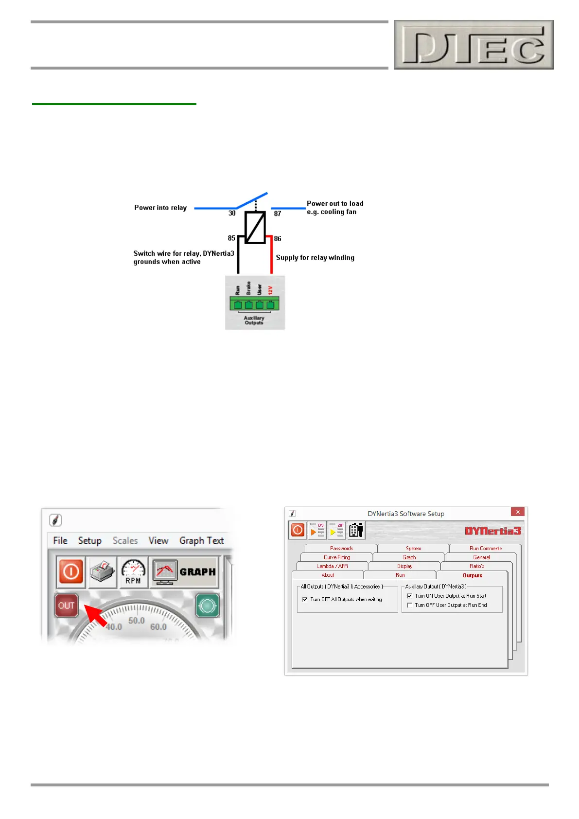
Auxiliary Connections
Connecting outputs if required
DYNertia3 has included the ability to control additional equipment. The auxiliary outputs ‘sink’ (switch to ground) when
active and can directly control a relay. A convenient battery voltage (12V) terminal is provided to simplify wiring.
The numbers shown below are international standards and are found labelled on most automotive style relays.
Note: DYNeria3 outputs can sink 500 mA each, this is more than sufficient for standard relays (~120mA); if you are
unsure then please test the relay current draw first. The 12V supply is likewise only designed for 3 standard relays.
Output functions
‘Run’ Output: Is on (grounded) when the dyno shaft is rotating above approximately 7.5 RPM or for as long as a Run
or function that involves dyno rotation is being performed. This can be used for safety control warning systems or
automatic fan controls etc.
‘User’ Output: Controlled output is available that is manually turned on or off from the software (‘Left’ click “OUT” icon
on both GRAPH and DYNO Windows) and can be used for any general purpose function e.g. remotely turning on a
cooling fan, pumps wheel clamps etc. In menu option “Setup/Software” it can be set to activate at start/end of a test Run,
press the “OUT” icon to turn off if set to only turn on at the test start.
Note: ‘Right’ click on “OUT” icon reveals additional
functions if optional ‘Load Controller’ is connected. See
manual chapter “Load Controllers” for details.
The “OUT” icon on GRAPH and DYNO Windows turns green to indicate the output is active.
Outputs (Brake and User) can be set to turn off upon exit. This ensures devices connected to the auxiliary output
terminals (see chapter “Outputs- Using”) can be left in a suitable state upon exiting the software.
This function extends to optional load controller also.