www.dtec.net.au
Chapter 4: ‘Setup’ Menu Options
Hardware- Setup Menu (cont.)
The entry screen for sensor/mass ratio is only revealed when an inertia dyno is
selected.
The entry screen for pulse generator is only revealed when a brake dyno is
selected AND the optional ‘Load Controller’ is configured (‘Linked’).
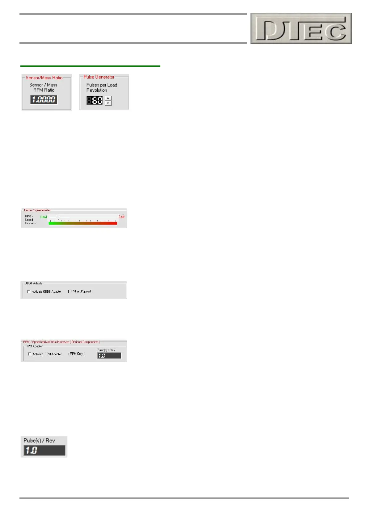
Sensor/Mass Ratio: On some special purpose dyno applications it may be that there is extremely low rotation speed
and therefore limited flywheel/roller timing data. This feature allows designs such as this to drive a sensor wheel via
gearing (or friction contact) at a higher RPM and thus can have the sensor trigger magnet speed applied rather than the
flywheel e.g. if the sensor magnet was spinning twice as fast as flywheel/roller then a value of 2 would be required.
It is also used where the sensor is not actually mounted on the flywheel/roller but on another shaft that rotates at a
different speed to the inertial mass.
Note: Trying to use this feature to allow triggering from multiple trigger targets on the flywheel/roller will result in poor
data quality; it will need excessive filtering to smooth out the ‘jitter’ from tolerances between your trigger targets.
Pulse Generator: The number of teeth on the trigger wheel is entered. See load controller chapter for details.
Tacho / Speedometer: The filtering speed determines the level of smoothing applied to the display. This has the effect
of displaying values that are not so wildly changing due to small cyclic variations in engine firing and dyno mechanical
tolerances.
Tip- Too large a ‘Smoothing’ numbers and disturbances that may be of interest can be hidden
OBDII Adapter input for Engine RPM and vehicle speed: If you have the optional OBDII interface (not available at
time of this manual) then you can choose to have this data used for various functions rather than just the calculated
RPM and speed (which is derived from the main flywheel/roller speed sensor).
RPM Adapter input for Engine RPM: If you have a suitable input adapter (such as DTec’s ‘RPM Adapter’) or sensor
connected to DYNertia3’s RPM Adapter input then you can choose to have this engine RPM value used for various
functions rather than just the calculated RPM (which is derived from the main flywheel/roller speed sensor).
NEVER connect ignition system directly to the RPM Adapter input!
RPM Adapter input is required if ‘slip’ analysis is to be performed. ‘Slip’ is dyno RPM compared to engine RPM, this is
handy for checking clutch engagement RPM or looking for loss of tyre traction on a chassis dyno.
It is important that if the RPM Adapter input is used then the number of pulses received that
represents a single engine rotation must be entered. It can be fractional e.g. 4 strokes only fire every
0.5 rev (which is once every 2 revolutions!) so “0.5” would be entered (2 stroke = “1”)
NOTE: Read the chapter “RPM Input Options” chapter for full setup details and “Inputs-
Using” chapter for connection!