www.dtec.net.au
Chapter 14: Inputs- Using
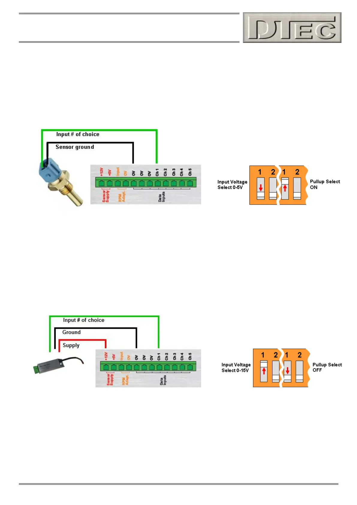
Resistive sensor connection
Inexpensive resistive sensors (resistance changes with temperature) can easily be connected thanks to the ‘Pullup’
switch and easy sensor calibration procedure. Ensure you switch the appropriate ‘Pullup’ switch to ON. This will connect
a 1KΩ resistor inside DYNertia3 between the input and 5V supply, this is required for resistive sensors.
Many sensors such as those from Bosch or Delco are pre-calibrated in DYNertia3 software. Check the settings in the
‘Setup’ menu under ‘Sensor Configuration’; this is covered at the end of this chapter.
Connection of DTec’s ‘Thermo-Amp’ thermocouple amplifier (for K-type sensors)
Thermocouples only produce tiny voltages so these are greatly amplified before use. This means they are very sensitive
to electrical noise also being amplified. Thermo-Amp and DYNertia3 take measures to prevent this but care is still
needed to get quality data. Avoid running near ignition system wiring and it is greatly preferable to use ‘isolated’ sensors,
these do not contact the earth (ground) of the vehicle and therefore connect only to Thermo-amp directly. Particular
problems could arise when using ‘spark plug washer’ type sensor probes, additionally if they are grounded and not
isolated type.
Note: For Thermo-Amp to read to 1200ºC the sensor supply will need to be 12V or greater. If only measuring to 500 ºC
then it can be powered from Dynertia3’s 5V supply terminal. Check the in the ‘Setup’ menu under ‘Sensor Configuration’
that Thermo-Amp is selected. This is covered at the end of this chapter. For the 0-500 C range set the input range on
DYNertia3 to 5V and not the 15V as shown above, this is as we have configured the ‘sensor list’ to allow a higher
resolution at lower temperatures.