www.dtec.net.au
Chapter 16: Load Controllers
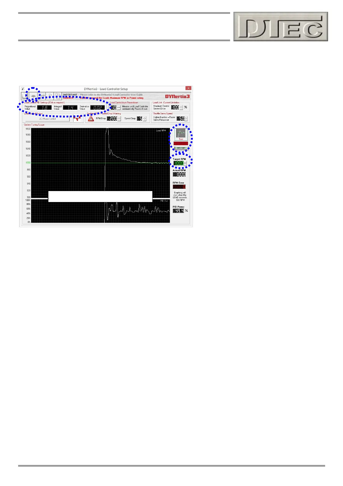
Poor tuning (large PID power variations)
Load control system commissioning (cont.)
Tip-Tunning a PID takes patience and time, best not done with a highly stressed race engine! Change one value at a
time and check/learn the behaviour. Consider your next change rather than ‘blindly’ changing numbers.
Setup procedure is-
Set a desired (‘Target’) RPM/speed (above the
‘Actual RPM/speed’)
Press the ‘Test’ button to start graphing
Accelerate the vehicle and it should hold steady at
the target RPM, observe the system behaviour.
Stop the test (press ‘Test’ again)
Make changes to the P, I or D value
Upload the new data into the control unit with the
‘Upload’ button (Arrow icon- top left) and re-test.
Tip-Watching the PID output on the lower trace
is important to see what the controller is actually
doing to correct the error, it is effectively the
current applied to the brake.
You can see above that with these values on this particular dyno that the RPM overshoots quite a bit and then stabilises
well after a small time. It needs tunning, the PID power values output to maintain the constant RPM are large and could
cause torque fluctuations (especially when ramp testing) as the brake continually applies/releases hard.
Tip- The PID values are multipliers (i.e. they multiply the effect of the correction). So make very small changes.
Proportional value-
Output is adjusted based on the present error, larger error means larger correction.
P is generally used to take care of the bulk of the correction. If only P is used it won’t settle on the target (offset).
Too high and overcompensates to a change (overshoots, possible oscillation, unstable)
Too low and won’t react enough to changes
Tip- Keep value low enough to avoid oscillation, trade off will be time to settle (I value can help).
Integral value-
Output based on accumulation of past errors (i.e. the size and duration of the error).
Determines the speed that it reaches the target and gradually cancels longer term errors (offset).
If only I used it oscillates out of control.
Too high and slow oscillation around target
Too low and won’t reach target fast enough and will have offset
Tip- Set just as needed for fast settling but not too much overshoot or oscillating
Derivative value-
Output based on rate of change (velocity), not amount of error.
Predicts the error so can compensate for system delays (by ‘overshooting’ momentarily when rapid changes), improves
settling time and stability.
Too low and slower to reach target and respond to small disturbances
Too high and rapid oscillation that puts ‘noise’ in the system
Tip- Start at very close to 0, D is often used in only very tiny amounts if at all as sensitive