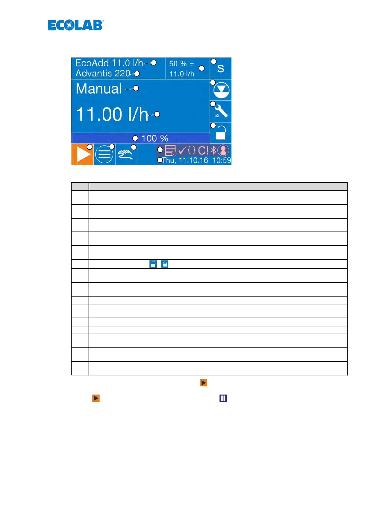
7.4 Display view during ongoing operation (example)
Fig. 23: Operating indicator (example)
Pos. Description
1
Pump name
Ä
Chapter 7.10.1 ‘Pump name’ on page 93
2
Maximum metering output in l/h (depending on the selected metering mode)
Ä
Chapter 7.8 ‘Metering mode’ on page 74
3
Metering mode (s, m, l, v)
Ä
Chapter 7.8 ‘Metering mode’ on page 74
4
Level display of the metering container
Ä
Chapter 9.4 ‘Changing a container - Empty signal’ on page 140
5
Maintenance display
Ä
Chapter 9.5 ‘Confirm the pump service’ on page 145
6
Display of access code
/ and elapsing timer for short-term cancellation of access code.
7
Variable status displays (OGM, calibration, batch, external enable, access code, Bluetooth, etc.)
Ä
Chapter 7.4.1 ‘Symbols in operating mode’ on page 70
8
Current, day, date and time
Ä
Chapter 7.10.2 ‘Date / time’ on page 94
9 Test button for manual metering and to bleed the system
10
Menu button for calling up the settings
Ä
Chapter 7.7 ‘Main menu’ on page 73
11 Start button in standby position (“ON” operating mode)
12 Display of the current percentage metering capacity
13
Current metering capacity
Ä
Chapter 9.3 ‘Set or reset the pump capacity in L’ on page 140
14
Current operating mode
Ä
Chapter 7.9 ‘Operating Mode’ on page 78
15
Metered chemical setting
Ä
Chapter 7.10.10 ‘Metering chemical’ on page 107
The pump is operated via the Start button (pos. 11).
If the pump is in operation, the [metering mode background] (pos. 3) flashes, and the Start
button (pos. 11) changes to the Pause button .
Control / Software
69 417102276 Rev. 5-02.2020