Maintenance 4. Cable
246 N6 Rev.2
The relay cable 1 is connected to the actuator unit and the motor unit on each joint.
Refer to the following steps depending on the positions to replace.
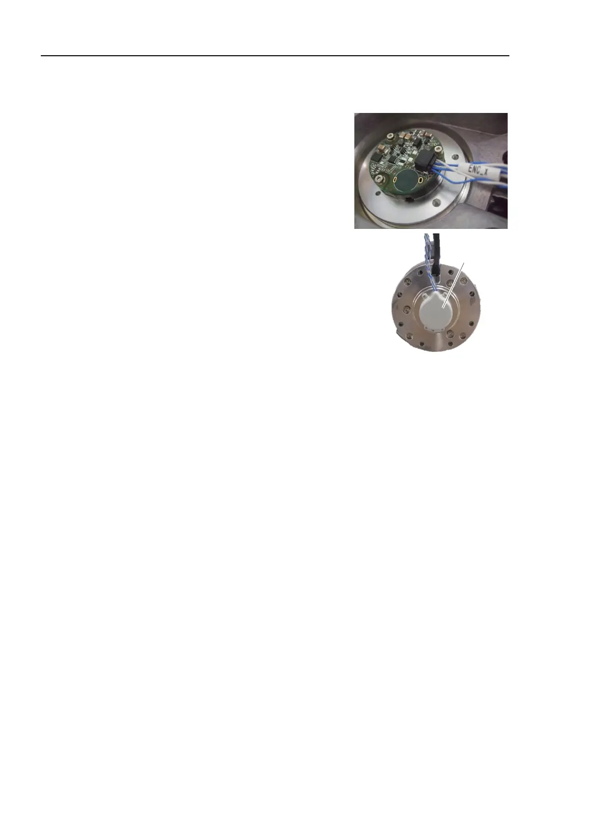
Connect the connector of the relay cable 1 to
the encoder.
Connector: ENC_x
Install the encoder cover.
Cross recessed head screws: 3-M2.5×6
Tightening torque: 0.2 ± 0.1 N·m
Install the Joint #1 actuator unit.
For details, refer to Maintenance 5.1 Replacing the Joint #1 Actuator Unit
for the Joint #1.
For details, refer to Maintenance 8. Calibration.

 Loading...


