Maintenance 4. Cable
248 N6 Rev.2
3
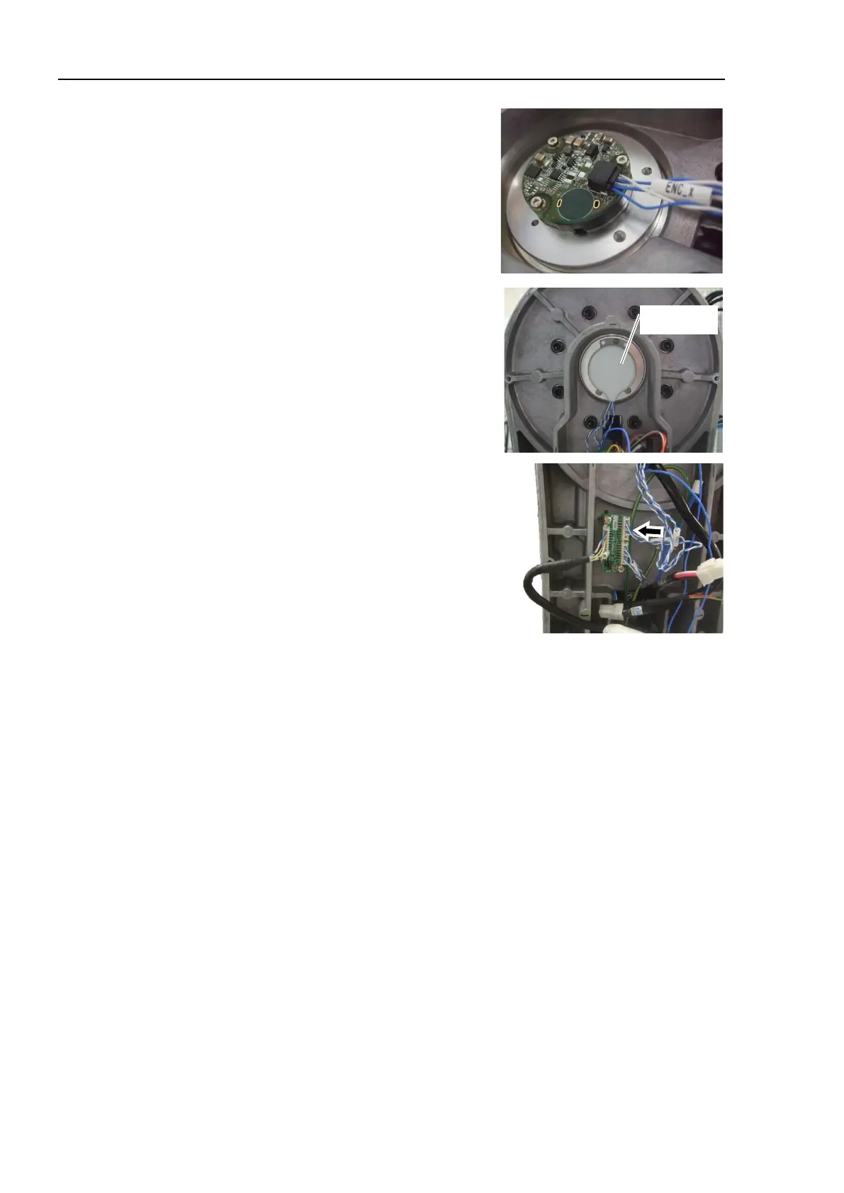
Connect the connector of the relay cable 1 to
the encoder.
Connector: ENC_x
Install the encoder cover.
Cross recessed head screws: 3-M2.5×6
Tightening torque: 0.2 ± 0.1 N·m
to the encoder board 2.
Connector: EB0x_CN2
Install the Arm #2 cover (2 covers).
For details, refer to the following sections:
Maintenance 3.7.1 N6-A1000** (Arm #2 Cover, Arm #1 Side)
Maintenance 3.7.2 N6- A850**R (Arm #2 Cover, Arm #1 Side)
For details, refer to Maintenance 4.6. M/C Cable.
6)
or the Joint #3.
For details, refer to Maintenance 8. Calibration.

 Loading...


