Maintenance 4. Cable
N6 Rev.2 249
4
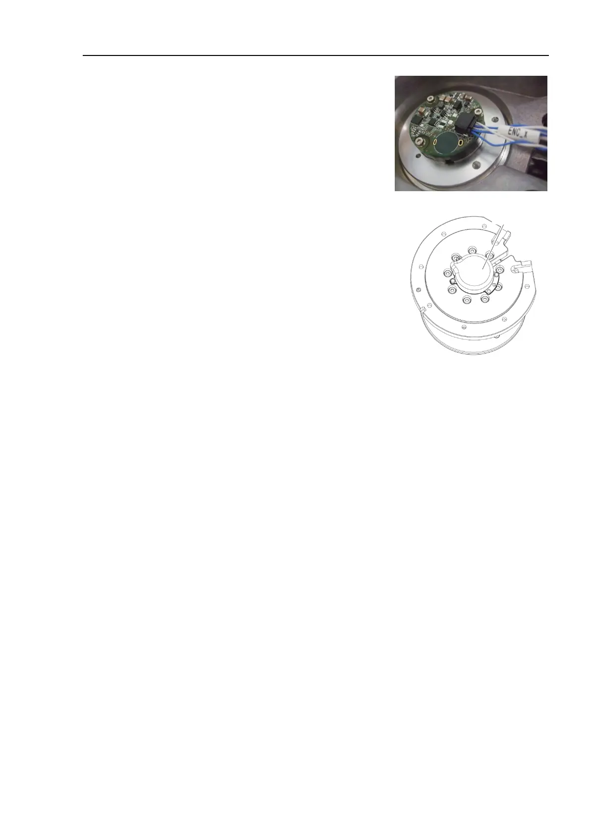
Connect the connector of the relay cable 1 to
the encoder.
Connector: ENC_x
Install the encoder cover.
Cross recessed head screws: 2-M2.5×6
Tightening torque: 0.2 ± 0.1 N·m
Install the Joint #4 actuator unit to the Arm #3.
For details, refer to the following sections:
Installation steps (38) through (52) in Maintenance 4.1 Cable Unit (N6-A1000*)
Cable direction Standard (backward).
Installation steps (41) through (55) in Maintenance 4.3 Cable Unit (N6-A850*R):
Cable direction Standard (backward).
e M/C cable.
For details, refer to Maintenance 4.6. M/C Cable.
5)
for the Joint #4.
For details, refer to Maintenance 8. Calibration.

 Loading...


