Maintenance 5. Actuator Units
N6 Rev.2 269
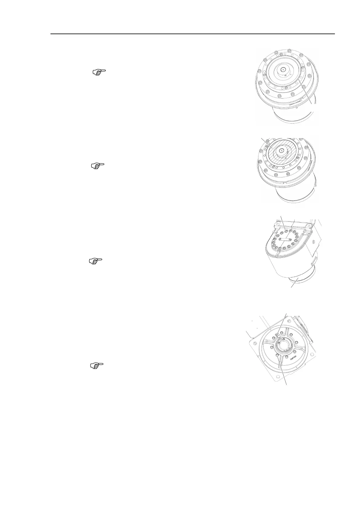
Installation
the attached O-ring to the
Apply a thin coat of grease to the O
-ring.
Grease: SK-1A
Joint #1
Actuator Unit
N6-A1000*
Cable direction:
Standard
(backward)
Apply the grease to the Joint #1 actuator unit.
Grease: SK-1A 15g
Be careful not to leak the grease from the
shaded area
shown in the right.
Install the Joint #1 actuator unit to the Arm #1.
Hexagon socket head cap bolts:
16-M5×35 (with plain washer)
Tightening torque: 10 ± 0.5 N·m
Be sure to have at least 2 people to perform the
operation since the parts being heavy.
Do not apply excessive shock to the parts.
-ring properly.
16-M5×35 (with plain washer)
4)
Hexagon socket head cap bolts:
8-M6×40 (with plain washer)
Tightening torque: 18 ± 0.9 N·m
When installing it, make sure to align the
directions of the hole of the base and the cable
exit of Joint #1 actuator unit.
ass the cables of the Joint #1 actuator unit
the base.
catch the cables.
8-M6×40 (with plain washer)

 Loading...


