Maintenance 5. Actuator Units
N6 Rev.2 301
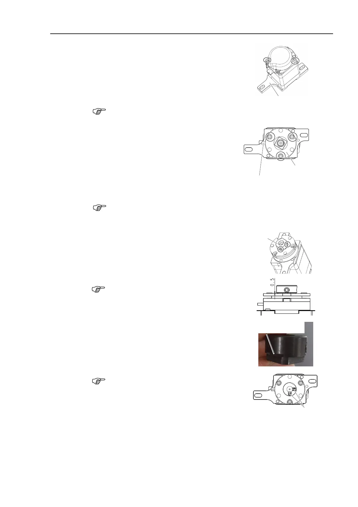
Installation
Joint #5
Motor Unit
(1)
Install the motor plate on the Joint #5 motor.
Hexagon socket head cap bolts: 2-M4×55
Tightening torque: 4.0 ± 0.2 N·m
Be careful of the installation direction of the motor plate.
Refer to the figure and
it in the proper position.
(2)
Install the Joint #5 electromagnetic brake on the
Joint #5 motor unit.
Install the spacer between
the hexagon socket head cap bolts and the Joint
#5 electromagnetic brake.
Hexagon socket head cap bolts: 3-M3×13
Tightening torque: 2.0 ± 0.1 N·m
Cables of
Electromagnetic brake
Direction to exit the cables of th
e electromagnetic brake is set.
Install the electromagnetic brake so that the cables of the electromagnetic brake
are
positioned in the same direction as the motor cables.
(3)
drive bosses on the motor shaft on
Hexagon socket set screws: 2-M4×4
Tightening torque: 2.4 ± 0.1 N·m
When fixing the drive bosses, make sure that the
clearance
between the drive bosses and the
brake will be 0.5mm.
feeler gauge (0.5 mm) of the drive boss to
(0.5 mm).
Cutout
Place in 90 degrees
aligned with the D-cut
surface on the motor shaft.
If the screw
positions are not correct, the side of part will get
damage and you cannot
pull out the part.
Hexagon socket set screws

 Loading...


