Ranger HRC™ operator´s manual – System description
Publ. No. TM 614 006 699 Rev B – ENGLISH (EN) – Oct 30. 2008 9
3.2.2 Junction Protocol Converter (JPC2)
The Junction Protocol Converter (JPC2) is the system control unit. The
System Software is executed from the JPC2 unit. The JPC2 can be con-
gured for stand-alone operation or congured into an IP network.
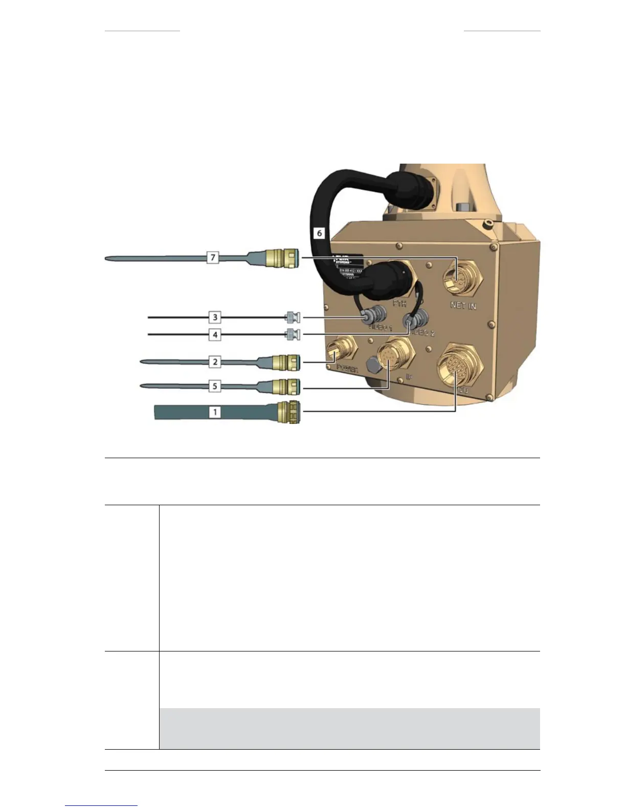
Figure 3.2 JPC2 connections.
JPC2 connections
Callout Description
1 System cable or JCU cable
When the system is controlled from a remotely located Joystick Control Unit, the
System cable is connected to the JCU connector (J1) on the JPC2 unit and to:
• the J5 connector on the Junction Box, or
• the J5 connector on the Power Box.
When the system is controlled from a directly connected Joystick Control Unit, the
JCU cable is connected to the JCU connector (J1) on the JPC2 unit and to the J10
connector on the Joystick Control Unit.
2 Power cable
The Power cable is connected to the POWER connector (J2) on the JPC2 unit and to
the Power Supply unit.
NOTE: The POWER connector (J2) on the JPC2 unit must not be used when
power is supplied via the System cable from the Junction Box or Power Box.
 Loading...
