FlexRay Module (FLEXRAYV4)
MFR4310 Reference Manual, Rev. 2
138 Freescale Semiconductor
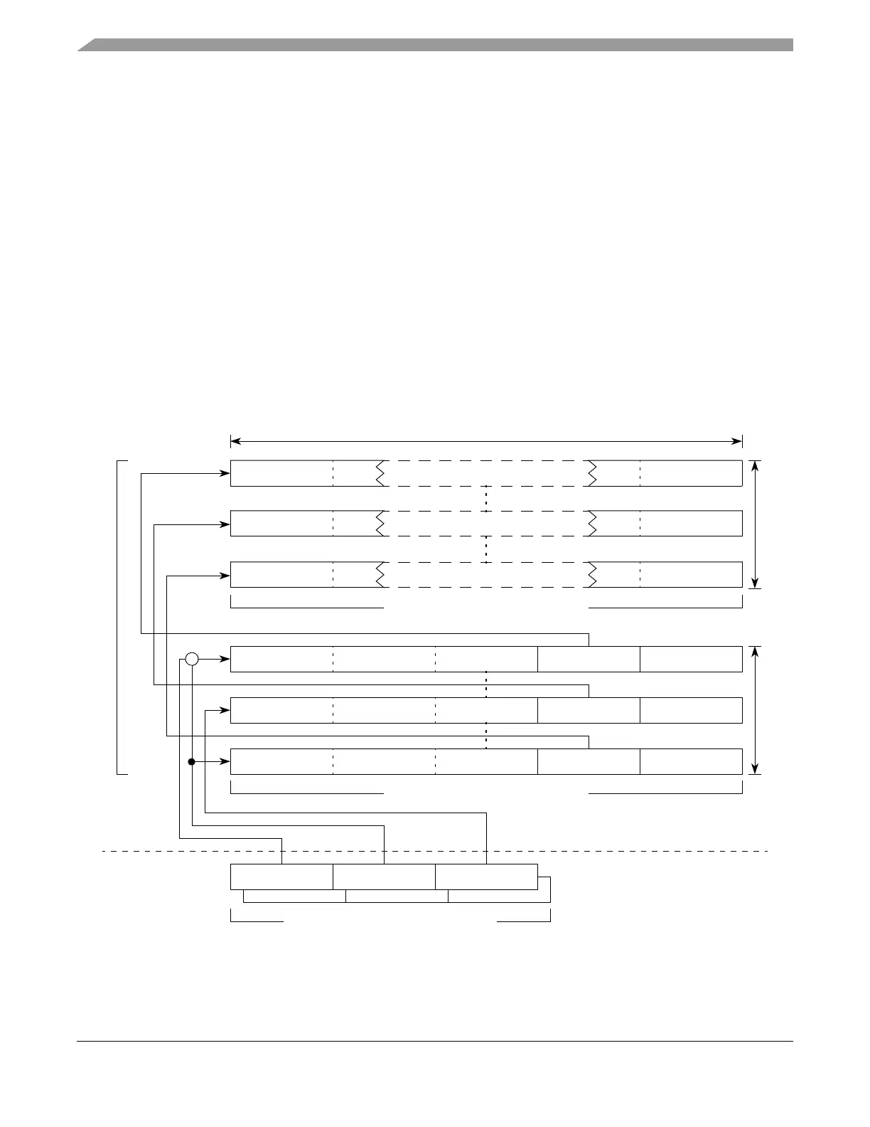
The connection between the receive FIFO control registers and the set of physical message buffers is
established by the start index field SIDX in the Receive FIFO Start Index Register (RFSIR), the FIFO
depth field FIFO_DEPTH in the Receive FIFO Depth and Size Register (RFDSR), and the read index field
RDIDX Receive FIFO A Read Index Register (RFARIR) / Receive FIFO B Read Index Register
(RFBRIR). The start address SADR_MBHF_1 of the first message buffer header field that belongs to the
receive FIFO in the FRM is determined according to Equation 3-4.
SADR_MBHF[1] = (RFSIR[SIDX] * 10) + 0x800 Eqn. 3-4
The start address SADR_MBHF[n] of the last message buffer header field that belongs to the receive FIFO
in the FRM is determined according to Equation 3-5.
SADR_MBHF[n] = ((RFSIR[SIDX] + RFDSR[FIFO_DEPTH]) * 10) + 0x800 Eqn. 3-5
NOTE
All message buffer header fields assigned to a receive FIFO must be a
contiguous region.
Figure 3-99. Receive FIFO Structure
RFBRIRRFDSR[B] RFSIR[B]
RFARIRRFDSR[A] RFSIR[A]
Frame Header[1]
Slot Status[1]Data Field Offset[1]
Receive FIFO Control Register
Message Buffer Header Fields
Message Buffer Data Fields
Frame Header[n]
Slot Status[n]Data Field Offset[n]
(min) RFDSR[ENTRY_SIZE] * 2 bytes
RFDSR[FIFO_DEPTH]
+
Frame Header[i]
Slot Status[i]Data Field Offset[i]
Frame Data[n]
SADR_MBDF[n]
Frame Data[i]
SADR_MBDF[i]
Frame Data[1]
SADR_MBDF[1]
RFDSR[FIFO_DEPTH]
SADR_MBHF[n]
SADR_MBHF[i]
SADR_MBHF[1]
FlexRay Memory