FlexRay Module (FLEXRAYV4)
MFR4310 Reference Manual, Rev. 2
Freescale Semiconductor 159
least one of the conditions mentioned above is fulfilled for these message buffers. The transition SA
changes the message buffer states from Idle to CCSa or from HLck to HLckCCSa. In each case, these
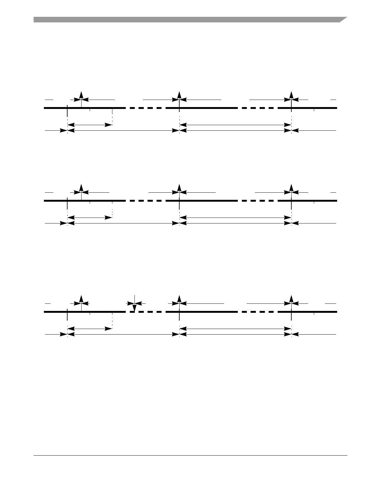
message buffers are used for null frame transmission in the next slot. A message buffer timing and state
change diagram for null frame transmission from Idle state is given in Figure 3-113.
Figure 3-113. Null Frame Transmission from Idle state
A message buffer timing and state change diagram for null frame transmission from HLck state is given
in Figure 3-114.
Figure 3-114. Null Frame Transmission from HLck state
If a transmit message buffer is in the CCSa or HLckCCSa state at the start of the transmission slot, a null
frame is transmitted in any case, even if the message buffer is unlocked or committed before the
transmission slot starts. A transmit message buffer timing and state change diagram for null frame
transmission for this case is given in Figure 3-115.
Figure 3-115. Null Frame Transmission from HLck state with unlock
Because the null frame transmission does not use the message buffer data, the application can lock/unlock
the message buffer during null frame transmission. A transmit message buffer timing and state change
diagram for null frame transmission for this case is given in Figure 3-116.
search[s+1]
M
T s
t
ar
t
MT start
SA
slot s
STS
SSS
CCSa CCNf
slot s+1
Idle
M
T s
ta
r
t
Idle
slot s+2
slot start
slot start
slot start
null frame transmit
search[s+1]
M
T s
t
art
M
T s
t
art
SA
slot s
STS SSS
HLckCCSa HLckCCNf
slot s+1
HLck
M
T
s
t
art
HLck
slot s+2
slot start
slot start
slot start
null frame transmit
search[s+1]
M
T star
t
MT s
t
art
SA
slot s
STS
SSS
HLckCCSa CCNf
slot s+1
HLck
MT start
Idle
slot s+2
slot start
slot start
slot start
HU
CCSa
null frame transmit