Clocks and Reset Generator (CRG)
MFR4310 Reference Manual, Rev. 2
230 Freescale Semiconductor
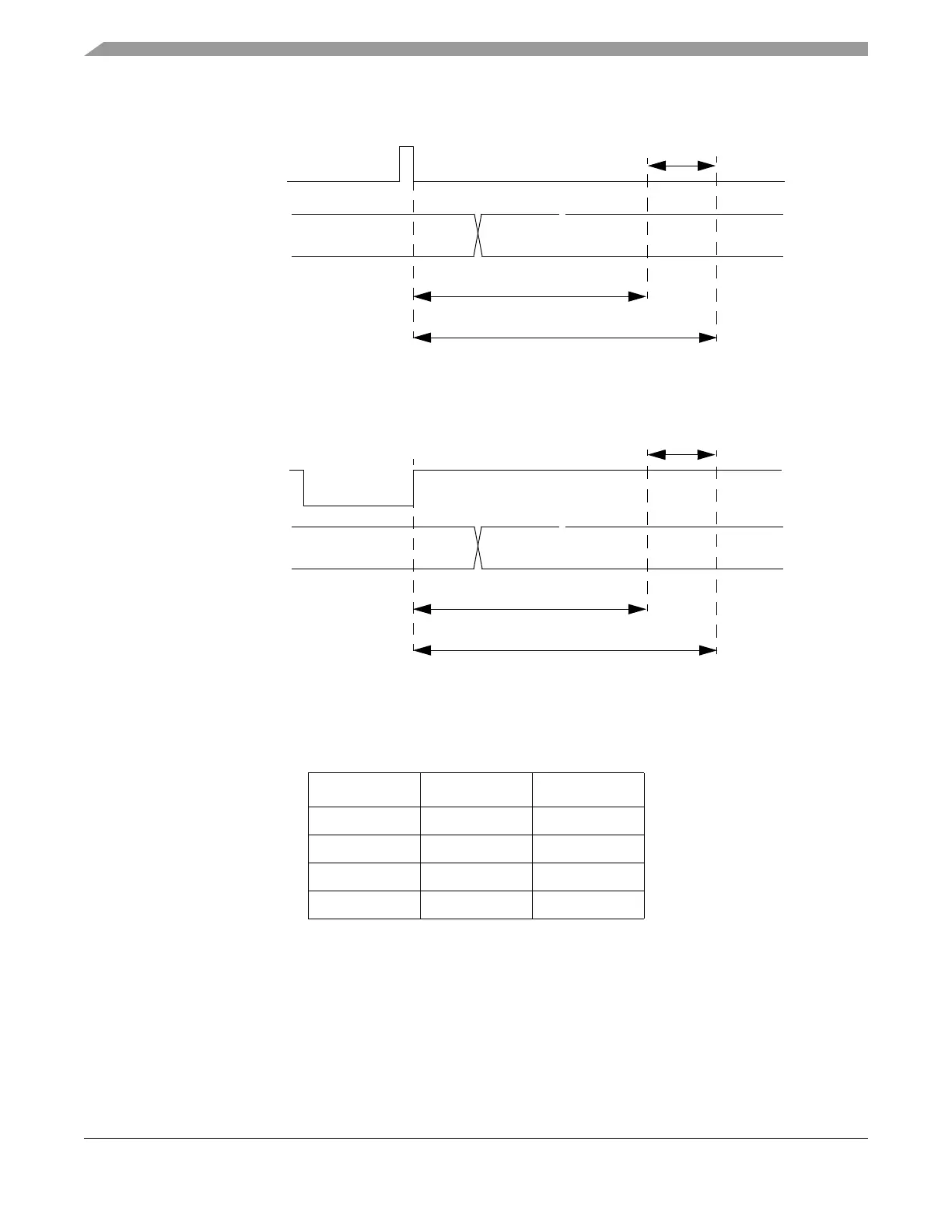
Figure 6-7. Interface Selection during Power-on or Low Voltage Reset or Clock Monitor Failure
Figure 6-8. Interface Selection during External Reset
Table 6-5 shows the interface selection encoding provided by the CRSR.ECS bit:
If, after the evaluation, the IF_SEL[1:0] are both low or both high, the CRG sets the CRSR.ECS bit to 1;
otherwise the CRG resets the CRSR.ECS bit to 0.
6.4.3 CLKOUT Mode Selection and Control
The CLKOUT mode selection is done when the DBG[3:2]/CLK_S[1:0] pins are in the CLK_S[1:0] mode.
In the DBG[3:2] modes the pads are outputs from the MFR4310 device.
Table 6-5. IF_SEL[1:0] Encoding by CRSR.ECS
IF_SEL1 IF_SEL0 CRSR.ECS
001
100
010
111
power-on reset or
IF_SEL[1:0]
low voltage reset or
clock monitor failure
~16380 EXTAL/CLK_CC periods
~16410 EXTAL/CLK_CC periods
Latching window
RESET#
IF_SEL[0;1]
~30 EXTAL/CLK_CC periods
~60 EXTAL/CLK_CC periods
Latching window