Electrical Characteristics
MFR4310 Reference Manual, Rev. 2
256 Freescale Semiconductor
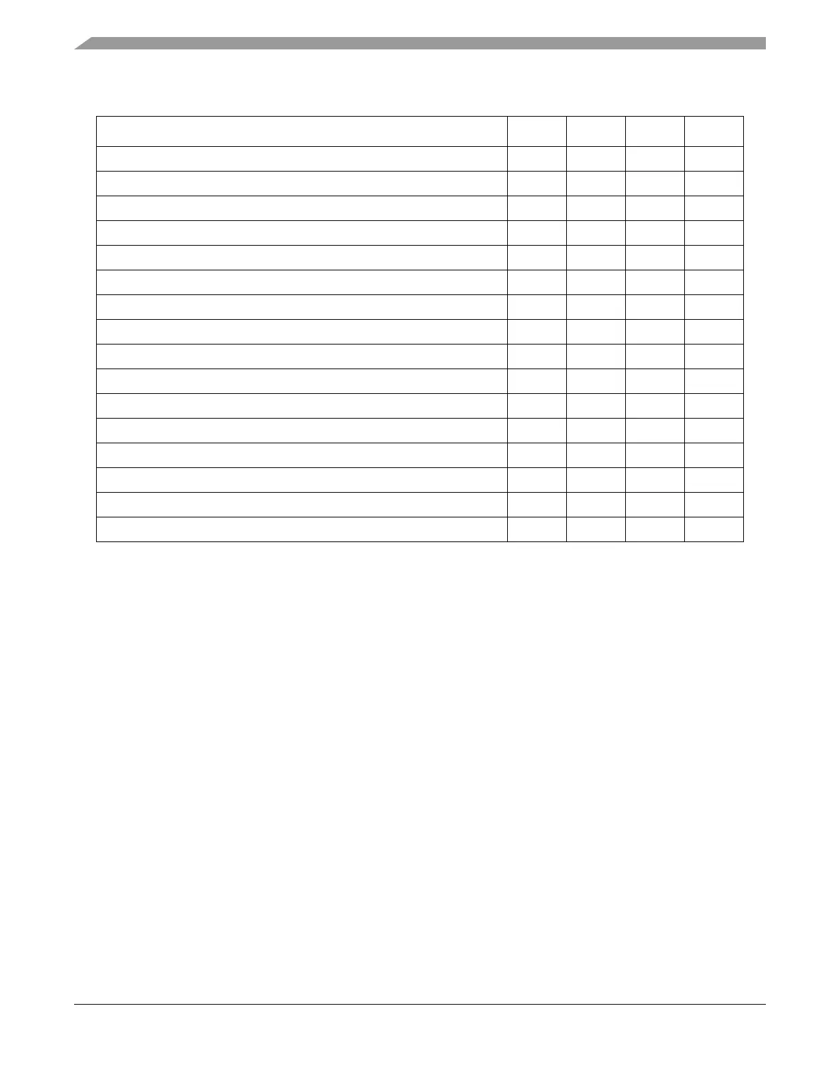
Table A-15. HCS12 Interface AC Switching Characteristics Over the Operating Range
1
1
Based on f
CLK_CC
= 40 MHz.
Characteristic Symbol Min Max Unit
Pulse width, ECLK_CC Low t
LEC
30 - ns
Pulse width, ECLK_CC High t
HEC
99
2
2
Depends on duty cycle of EXTAL/CLK_CC: t
HEC
= 99 + (t
CLK_CC
× 0.5) - t
CLK_CC_HIGH
, where t
CLK_CC
is the period in
ns of EXTAL/CLK_CC and t
CLK_CC_HIGH
is the period in ns of the high phase of EXTAL/CLK_CC.
-ns
Address valid time to ECLK_CC rise t
SA
11 - ns
Write Data delay time t
DDW
-70ns
Write Data hold time t
HDW
80 ns
RW_CC# delay time t
DRW
-7ns
RW_CC# valid time to ECLK_CC rise t
SRW
14 - ns
RW_CC# hold time t
HRW
2-ns
Data hold to address t
HDA
2-ns
Multiplexed Address hold time t
HA
2-ns
ECLK_CC high access time (ECLK_CC high to Read Data valid) t
DEC
50 90 ns
Read Data setup time t
SDR
13 - ns
Read Data hold time t
HDR
0-ns
Low strobe delay time t
DLS
-7ns
Low strobe valid to ECLK_CC rise t
SLS
14 - ns
Low strobe hold time t
HLS
2-ns