Clocks and Reset Generator (CRG)
MFR4310 Reference Manual, Rev. 2
Freescale Semiconductor 231
NOTE
The PIM block selects the DBG[3:2]/CLK_S[1:0] pads modes based on the
system reset signal.
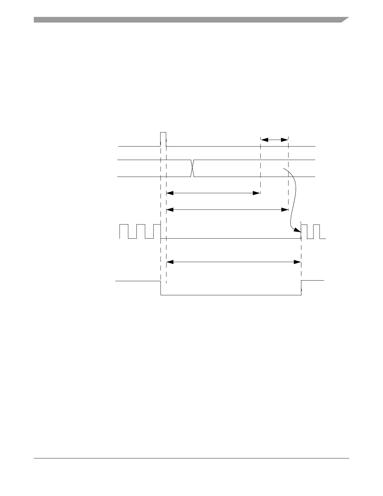
The CLKOUT mode selection is made upon the levels of the CLK_S[1:0] signals in the latching window
while a power-on, low voltage, clock monitor or external reset process is ongoing. The CRG latches the
CLK_S[1:0] signal values during the latching window as presented on Figure 6-9, Figure 6-10 and
Figure 6-11. The latched values are indicated in the CRSR.CDCV field.
Figure 6-9. CLKOUT Mode Selection and Control during Low-voltage Reset or Clock Monitor Failure
CLK_S[1:0]
low voltage reset or
clock monitor failure
~16380 EXTAL/CLK_CC periods
~16410 EXTAL/CLK_CC periods
Latching window
system reset
~16420 EXTAL/CLK_CC periods
CLKOUT