FlexRay Module (FLEXRAYV4)
MFR4310 Reference Manual, Rev. 2
Freescale Semiconductor 179
message buffers can be RC1-reconfigured when in the HDis or HDisLck state. Double transmit message
buffers can be RC1-reconfigured if both the transmit side and the commit side are in the HDis state.
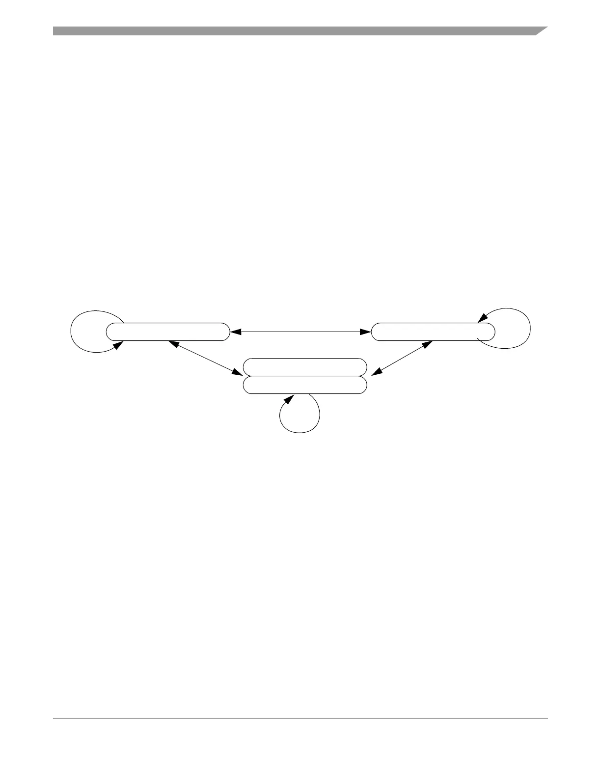
3.4.8.1.2 Buffer Type Not Changed (RC2)
A reconfiguration does not change the buffer type of the individual message buffer if the message buffer
buffer type bit MBCCSRn.MBT is not changed. This type of reconfiguration is denoted by RC2 in
Figure 3-127. It applies only to single transmit and receive message buffers. Single transmit and receive
message buffers can be RC2-reconfigured when in the HDis or HDisLck state.
3.4.8.1.3 Buffer Type Changed (RC3)
A reconfiguration does change the buffer type of the individual message buffer if the message buffer type
bit MBCCSRn.MBT is changed. This type of reconfiguration is denoted by RC3 in Figure 3-127. The RC3
reconfiguration splits one double buffer into two single buffers or combines two single buffer into one
double buffer. In the later case, the two single message buffers must have consecutive message buffer
numbers and the smaller one must be even. Message Buffers can be RC3 reconfigured if they are in the
HDis state.
Figure 3-127. Message Buffer Reconfiguration Scheme
3.4.9 Receive FIFO
This section provides a detailed description of the two receive FIFOs.
3.4.9.1 Overview
The receive FIFOs implement the queued receive buffer defined by the FlexRay Communications System
Protocol Specification, Version 2.1 Rev A. One receive FIFO is assigned to channel A, the other receive
FIFO is assigned to channel B. Both FIFOs work completely independent from each other.
The message buffer structure of each FIFO is described in Section 3.4.3.3, “Receive FIFO”. The area in
the FRM for each of the two receive FIFOs is characterized by:
• The index of the first FIFO entry given by Receive FIFO Start Index Register (RFSIR)
• The number of FIFO entries and the length of each FIFO entry as given by Receive FIFO Depth
and Size Register (RFDSR)
single RX single TX
double TX (commit side)
double TX (transmit side)
RC1
RC1
RC1
RC2
RC3RC3