Electrical Characteristics
MFR4310 Reference Manual, Rev. 2
254 Freescale Semiconductor
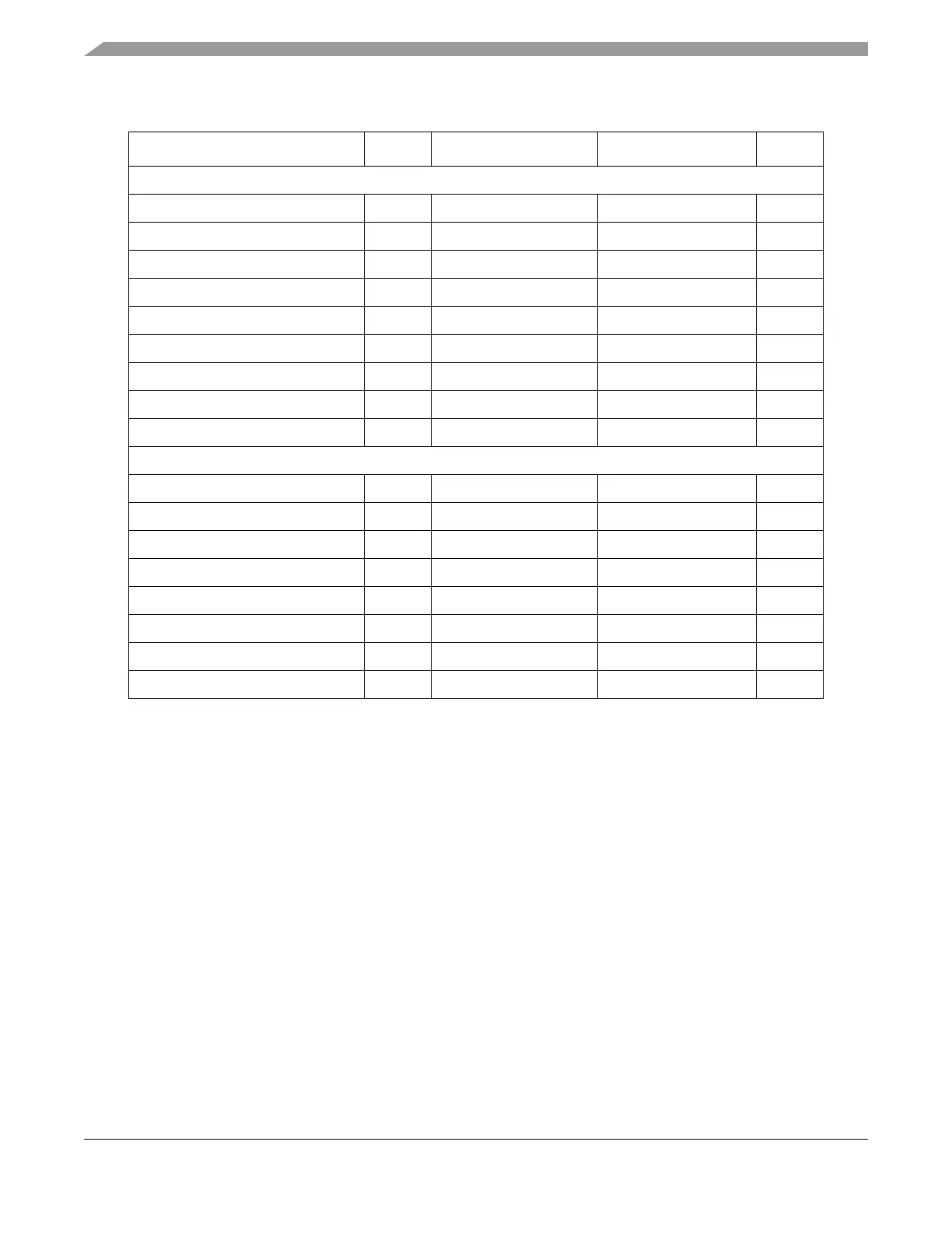
Table A-14. MPC Interface AC Switching Characteristics Over the Operating Range
1
1
t
CHICLK_CC
is the period in ns of the CHI and host interface clock CHICLK_CC.
Characteristic Symbol Min Max Unit
Read Cycle
Read Time Cycle t
RC
2.5 × t
CHICLK_CC
+ 32 ns
Address Setup Read t
SAR
5ns
Address Hold Read t
HAR
5ns
OE# LOW to Data valid t
DOE
2.5 × t
CHICLK_CC
+ 23 ns
OE# LOW time t
LOE
2.5 × t
CHICLK_CC
+ 27
2
2
Depends on duty cycle of the CHI and host interface clock: t
LOE
= (3.0 × t
CHICLK_CC
) - t
CHICLK_CC_HIGH
+ 27,
where t
CHICLK_CC_HIGH
is the period in ns of the high phase of the CHI and host interface clock.
ns
OE# HIGH time t
HOE
5ns
OE# LOW to Low-Z t
LZOE
5ns
OE# HIGH to High-Z t
HZOE
15 ns
BSEL[1:0]# HIGH to OE# LOW t
BSELOE
1 × t
CHICLK_CC
ns
Write Cycle
Write Time Cycle t
WC
3 × t
CHICLK_CC
+ 10 ns
Address Setup Write t
SAW
5ns
Address Hold Write t
HAW
5ns
Data Setup t
SD
5ns
Data Hold t
HD
5ns
BSEL[1:0]# LOW time t
LBSEL
1.5 × t
CHICLK_CC
+ 5 ns
BSEL[1:0]# HIGH time t
HBSEL
0.5 × t
CHICLK_CC
+ 5 ns
OE# HIGH to BSEL[1:0]# LOW t
OEBSEL
0ns