Device Overview
MFR4310 Reference Manual, Rev. 2
Freescale Semiconductor 43
While the CLK_S[1:0] levels are being latched, the output drive control is
disabled, and the internal pulldown resistors are connected to the pins.
2.4.3.20 EXTAL/CC_CLK — Crystal Driver, External Clock Pin
This pin can act as a crystal driver pin (EXTAL) or as an external clock input pin (CC_CLK). On reset, the
device clock is derived from the input frequency on this pin. Refer to Figure 2-3 for Pierce oscillator
connections and Figure 2-4 for external clock connections. See also Chapter 7, “Oscillator (OSCV2)”.
2.4.3.21 XTAL — Crystal Driver Pin
XTAL is a crystal driver pin. Refer to Figure 2-3 for oscillator connections and Figure 2-4 for external
clock connections. See also Chapter 7, “Oscillator (OSCV2)”.
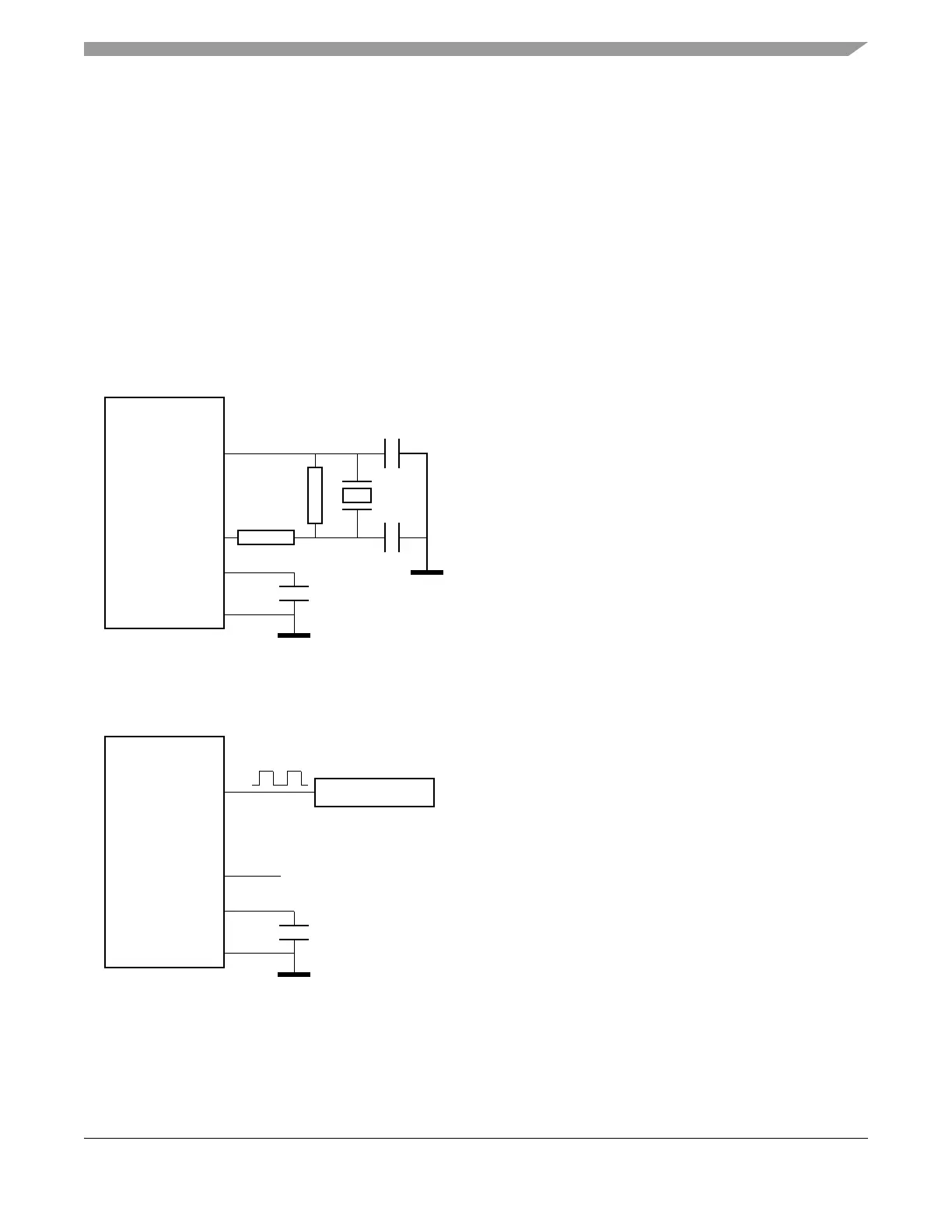
Figure 2-3. Oscillator Connections
Figure 2-4. External Square Wave Clock Generator Connection
Where:
• Q = 40 MHz crystal
• Rb is in the range 1M – 10 MΩ
• Rs is a lower value, which can be 0 Ω
•C1 = C2
• See crystal manufacturer’s product specification for
recommended values
Oscillator supply output capacitor C3 = 220 nF
MFR4310
XTAL
EXTAL
VDDOSC
VSSOSC
Q
C2
C1
Rb
Rs
VSSOSC
VSSOSC
C3
MFR4310
XTAL
EXTAL
VDDOSC
VSSOSC
VSSOSC
C3
Where:
G = 40 MHz CMOS-compatible External Oscillator
(VDDOSC-Level)
CLKOUT
G
Not connected
(left open)