FlexRay Module (FLEXRAYV4)
MFR4310 Reference Manual, Rev. 2
192 Freescale Semiconductor
3.4.16 Strobe Signal Support
The FlexRay module provides a number of strobe signals for observing internal protocol timing related
signals in the protocol engine. The signals are listed and described in Table 3-12.
3.4.16.1 Strobe Signal Assignment
Each of the strobe signals listed in Table 3-12 can be assigned to one of the four strobe ports using the
Strobe Signal Control Register (STBSCR). To assign multiple strobe signals, the application must write
multiple times to the Strobe Signal Control Register (STBSCR) with appropriate settings.
To read out the current settings for a strobe signal with number N, the application must execute the
following sequence:
1. Write to STBSCR with WMD equaling 1 and SEL equaling N. (updates SEL field only)
2. Read STBCSR.
The SEL field provides N and the ENB and STBPSEL fields provides the settings for signal N.
3.4.16.2 Strobe Signal Timing
This section provides detailed timing information of the strobe signals with respect to the protocol engine
clock.
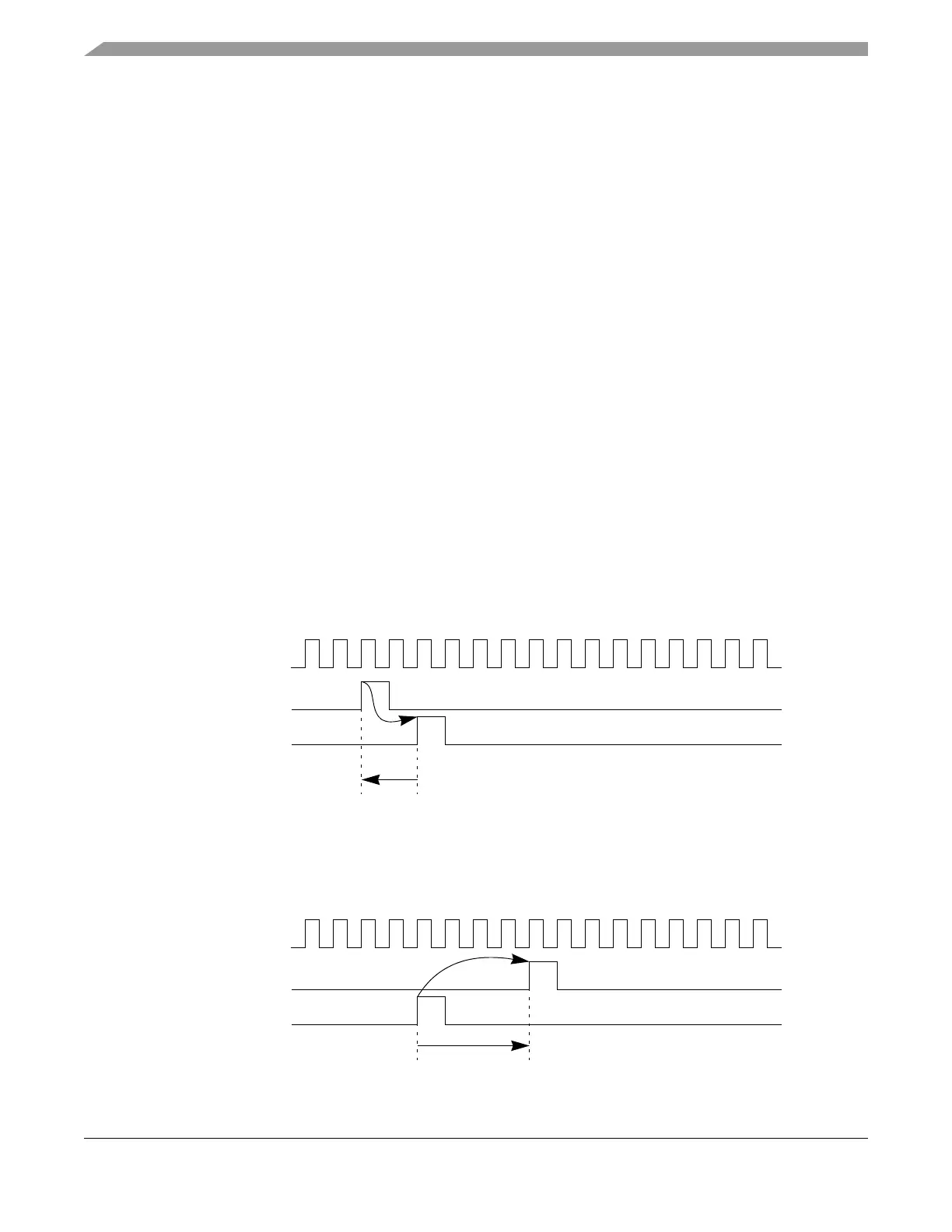
The strobe signals display internal PE signals. Due to the internal architecture of the PE, some signals are
generated several PE clock cycles before the actual action is performed on the FlexRay Bus. These signals
are listed in Table 3-12 with a negative clock offset. An example waveform is given in Figure 3-136.
Figure 3-136. Strobe Signal Timing (type = pulse, clk_offset = -2)
Other signals refer to events that occurred on the FlexRay Bus some cycles before the strobe signal is
changed. These signals are listed in Table 3-12 with a positive clock offset. An example waveform is given
in Figure 3-137.
Figure 3-137. Strobe Signal Timing (type = pulse, clk_offset = +4)
PE Clock
Strobe Signal
FlexRay Bus Event
-2
PE Clock
Strobe Signal
FlexRay Bus Event
+4