FlexRay Module (FLEXRAYV4)
MFR4310 Reference Manual, Rev. 2
184 Freescale Semiconductor
A received valid frame in the dynamic segment with the payload preamble indicator bit PPI set to 1 and
with the message ID MID (the first two bytes of the payload) passes the RX FIFO Message ID Acceptance
Filter if Equation 3-14 is fulfilled.
Eqn. 3-14
The RX FIFO Message ID Acceptance Filter can be configured to accept all frames by setting
• RFMIDAFMR.MIDAFMSK:= 0x000
Using the settings above, Equation 3-14 is always fulfilled and all frames pass.
3.4.10 Channel Device Modes
This section describes the two FlexRay channel device modes that are supported by the FlexRay module.
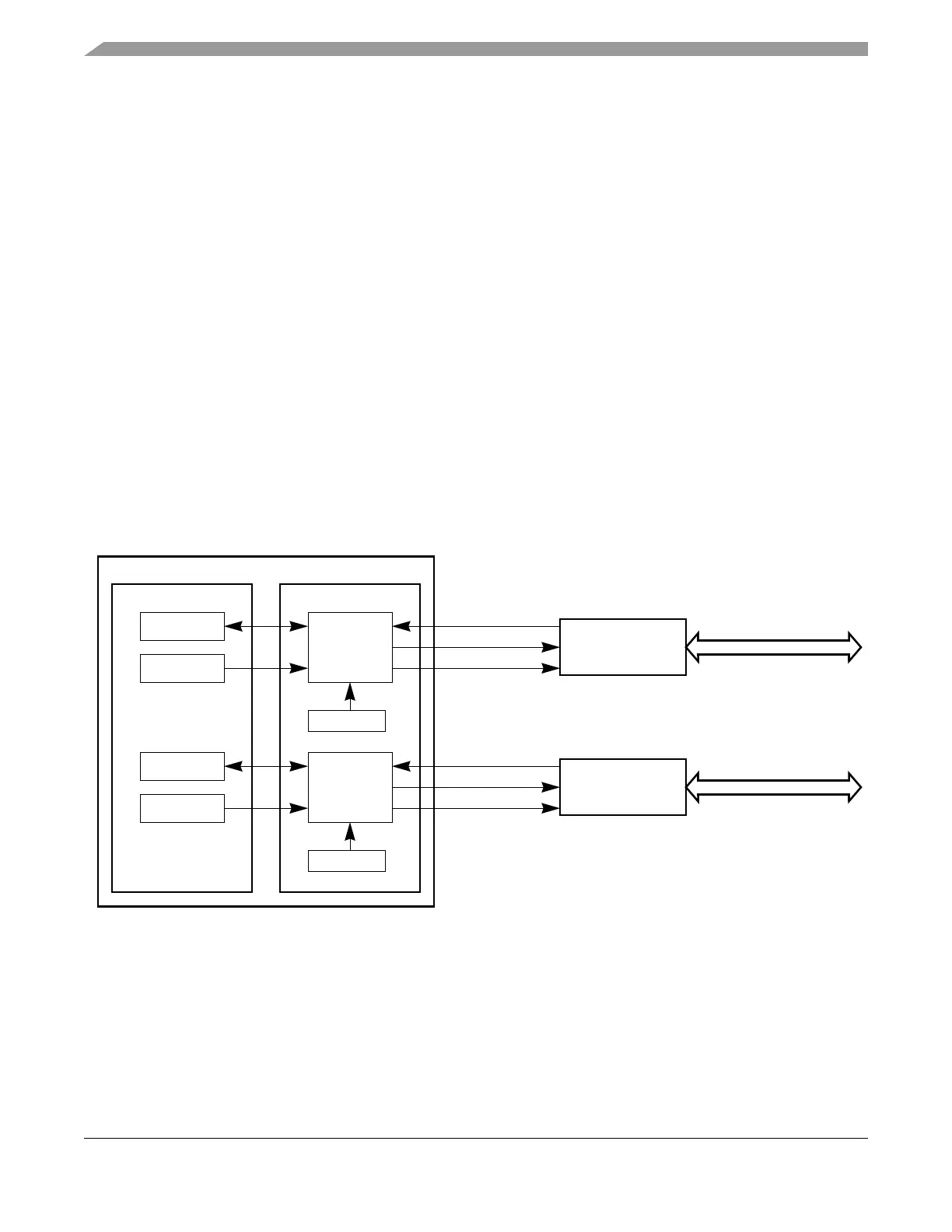
3.4.10.1 Dual Channel Device Mode
In the dual channel device mode, both FlexRay ports are connected to physical FlexRay bus lines. The
FlexRay port consisting of RXD_BG1, TXD_BG1, and TXEN1# is connected to the physical bus channel
A and the FlexRay port consisting of RXD_BG2, TXD_BG2, and TXEN1# is connected to the physical
bus channel B. The dual channel system is shown in Figure 3-129.
Figure 3-129. Dual Channel Device Mode
3.4.10.2 Single Channel Device Mode
The single channel device mode supports devices that have only one FlexRay port available. This FlexRay
port consists of the signals RXD_BG1, TXD_BG1, and TXEN1# and can be connected to the physical bus
channel A (shown in Figure 3-130) or the physical bus channel B (shown in Figure 3-131).
MID RFMIDAFMR MIDAFMSK[]∧ RFMIDAFMR MIDAFVAL[]RFMIDAFMR MIDAFMSK[]∧=
CHI
PE
cfg(A)
reg(A)
cCrcInit[A]
cCrcInit[B]
cfg(B)
reg(B)
channel 0
channel 1
FlexRay Channel A
FlexRay Bus Driver
Channel A
RXD_BG1
TXD_BG1
TXEN1#
FlexRay Channel B
FlexRay Bus Driver
Channel B
RXD_BG2
TXD_BG2
TXEN2#
FlexRay Module