Clocks and Reset Generator (CRG)
MFR4310 Reference Manual, Rev. 2
Freescale Semiconductor 229
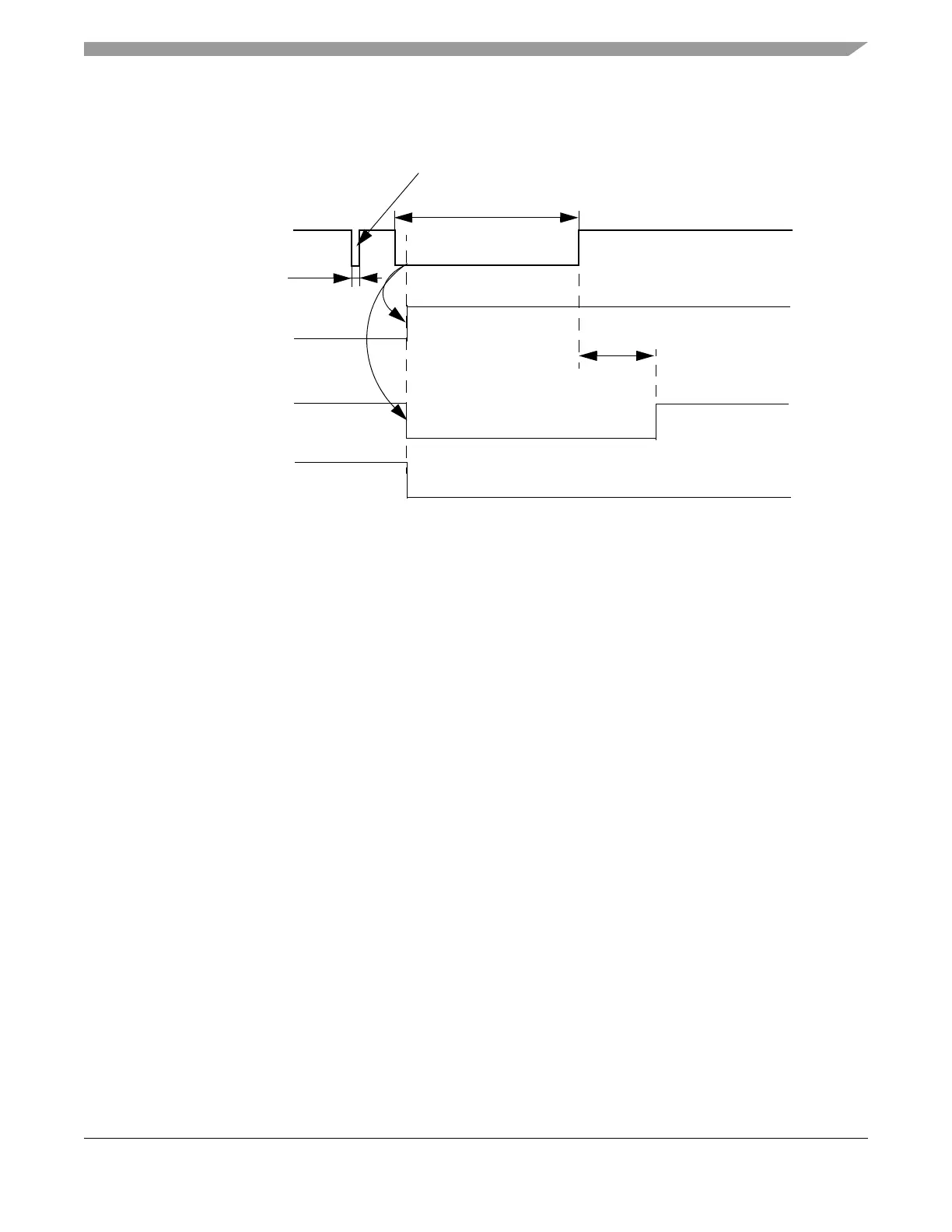
Figure 6-6. External Reset
6.4.1.4 RESET# Glitch Filter
The CRG has a built-in RESET# glitch filter to avoid device reset caused by glitches on the RESET# line.
It removes glitches with durations less than or equal to PW
RSTG
. Figure 6-6 illustrates an external reset
sequence with a glitch filtered out by the glitch filter.
Timing characteristics of the glitch filter can be found in Table A-11.
6.4.2 Interface Selection
The interface mode selection is done when the TXD_BG[1:2]/IF_SEL[1:0] pins are in the IF_SEL[1:0]
mode. In the TXD_BG[1:2] modes the pads are outputs from the MFR4310 device.
NOTE
The PIM block selects the TXD_BG[1:2]/IF_SEL[1:0] pads modes based
on the system reset signal.
6.4.2.1 Interface and AMI Clock Selection
The interface selection is made upon the levels on the bus signal IF_SEL[1:0] while a power-on, low
voltage, clock monitor (if enabled) or external reset process is ongoing. The CRG latches the IF_SEL[1:0]
during the latching window as presented in Figure 6-7 and Figure 6-8.
System Reset
~70 EXTAL/CLK_CC periods
CRSR.ERIF
INT_CC#
RESET#
A glitch filtered out by
the RESET# Glitch Filter
≤ PW
RSTG
≥ PW
RSTL