Electrical Characteristics
MFR4310 Reference Manual, Rev. 2
Freescale Semiconductor 249
A.3 Reset and Oscillator
This section summarizes the electrical characteristics of the various startup scenarios for the Oscillator.
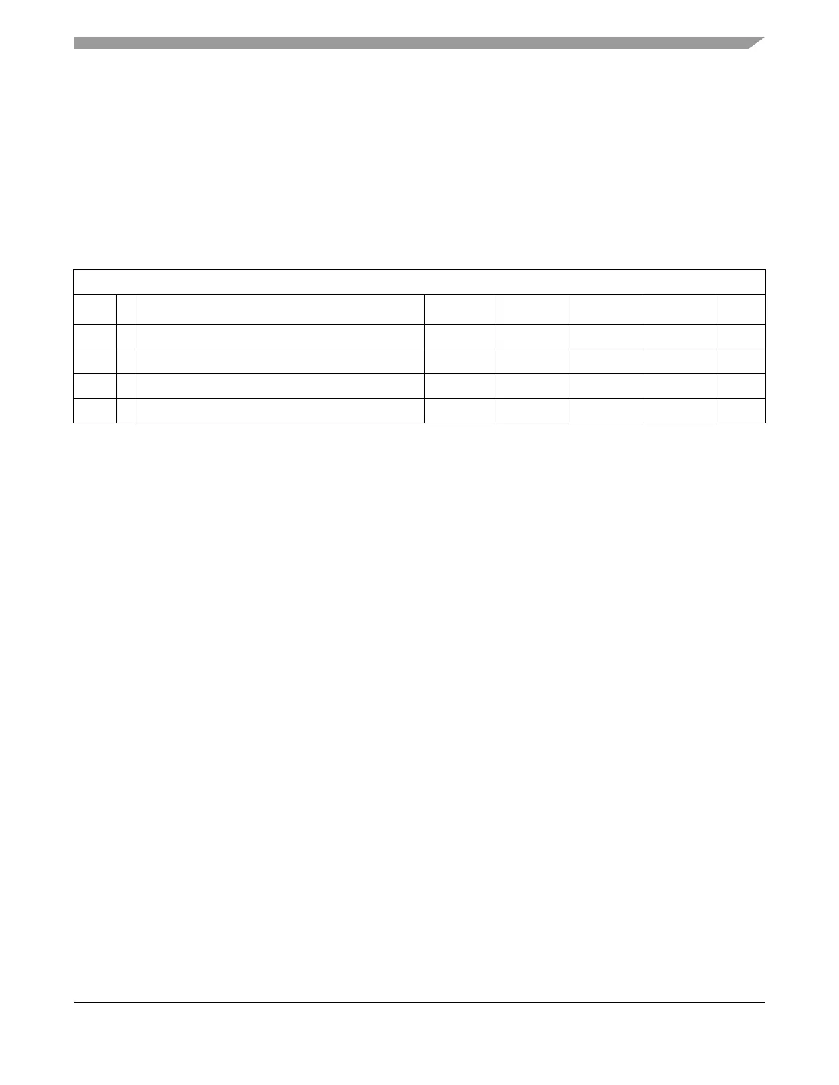
A.3.1 Startup
Table A-11 summarizes several startup characteristics explained in this section. Detailed description of the
startup behavior can be found in Chapter 6, “Clocks and Reset Generator (CRG)”.
A.3.1.1 POR
The release level V
PORD
(see Table A-9) and the assert level V
PORA
(see Table A-9) are derived from the
V
DD
supply. They are also valid if the device is powered externally. After releasing the POR reset the
oscillator is started.
A.3.1.2 LVR
The assert level V
LVRA
(see Table A-9) is derived from the V
DD
supply. After releasing the LVR reset, the
oscillator is started.
A.3.1.3 External Reset
When external reset is asserted for a time greater than PW
RSTL
the CRG module generates an internal
reset, and the CC starts operations, if there was an oscillation before reset.
Table A-11. Startup Characteristics
Conditions are shown in Ta bl e A -4 unless otherwise noted
Num C Rating Symbol Min Typ Max Unit
1 T POR deassert level V
PORD
- - 2.07 V
2 T POR assert level V
PORA
0.97 - - V
3 D Reset input pulse width, minimum input time PW
RSTL
14 - - ns
4 D Filtered glitch duration PW
RSTG
--3ns