Device Overview
MFR4310 Reference Manual, Rev. 2
50 Freescale Semiconductor
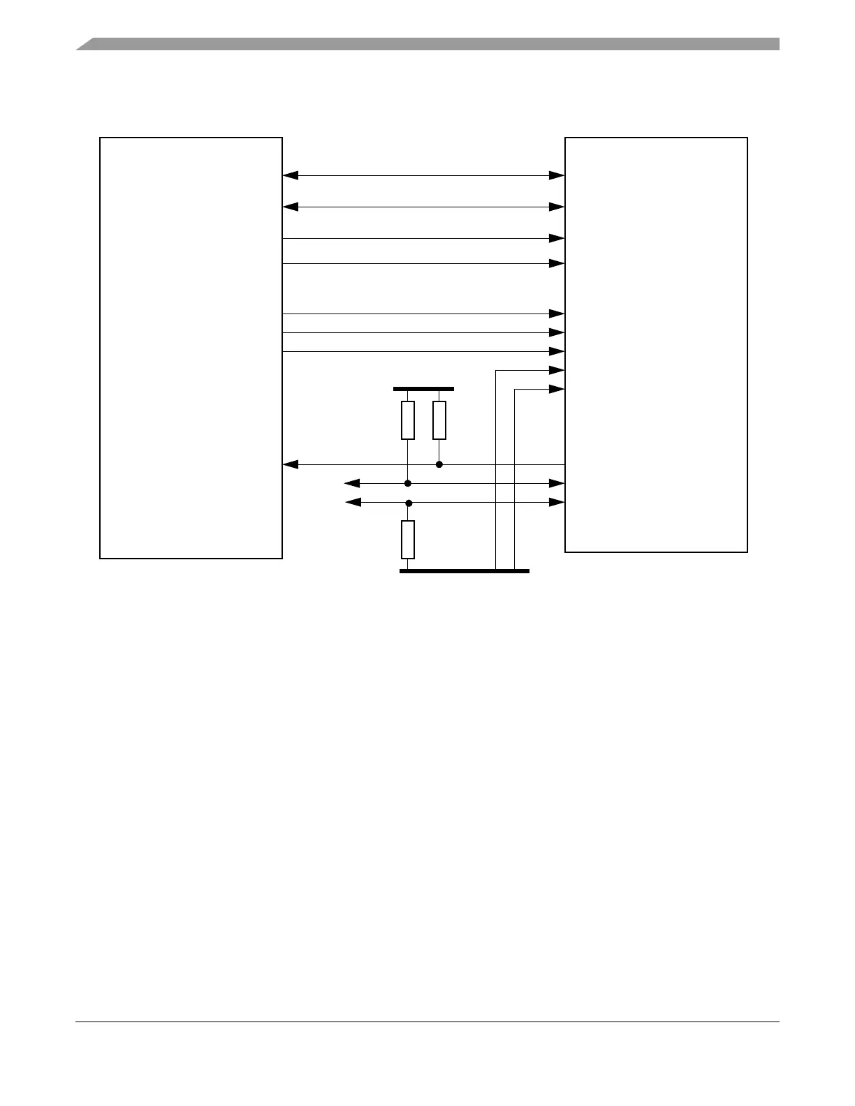
2.7.1.2 Asynchronous Memory Interface with DSP 56F83 (Hawk) Family
Figure 2-6. AMI Interface with DSP 56F83 (Hawk) Family
2.7.1.3 Asynchronous Memory Interface Timing
See Section A.4, “Asynchronous Memory Interface Timing” for timing characteristics of the AMI
interface.
2.7.2 MPC Interface
Figure 2-7 shows how to connect the CC to a microcontroller using the MPC interface. In this case, the
host bus pins have the meanings shown in Table 2-9.
• Data exchange in MPC mode is controlled by the CE#, BSEL[1:0]#, and OE# inputs.
• The MPC interface is implemented as an asynchronous memory slave module, thus enabling the
fast interfacing with a variety of microcontrollers.
• The MPC interface decodes its internal register addresses with help of the chip select signal CE#
and the address lines A[12:1].
• The MPC interface accepts only aligned 16-bit read and 8- or 16-bit write transactions. The MPC
interface does not support 8-bit read accesses.
MFR4310DSP56F83xx Family
D0
D15 D15
D0
A1
A11 A12
A0
…
…
…
…
WE#
CE#
OE#
WR#
CSn#
RD#
INT_CC#
TXD_BG2/IF_SEL0
TXD_BG1/IF_SEL1
IRQn#
VDDXn
PL Interface
VSSXn
BSEL1#
BSEL0#