Device Overview
MFR4310 Reference Manual, Rev. 2
54 Freescale Semiconductor
NOTE
AMI-only inputs A[9:7], BSEL[1:0]#/DBG[0:1] (if the debug strobes are
disabled), and CHICLK_CC are not used when the HCS12 interface is
selected and must be driven to logic 0 or logic 1 (i.e. they must not be left
floating).
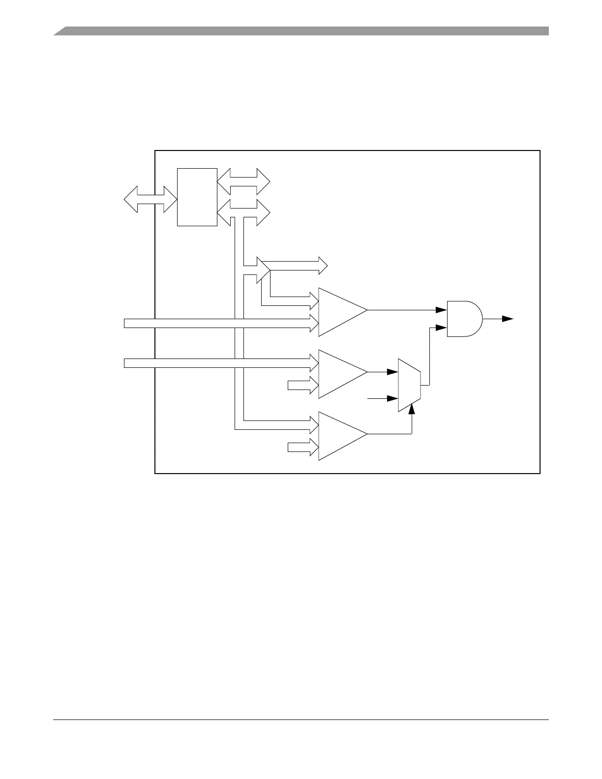
Figure 2-8. HCS12 Interface Address Decoding and Internal Chip Select Generation
16 bit
Address
/Data
Multi-
plexer
16 bit
16 bit
10 bit
3 bit
3 bit
6 bit
6 bit
2 bit
2 bit
&
1
0
1
000000
01
DATA[0:15]
DATA SIGNALS
ADR[0:15]
ADDRESS SIGNALS
ADR[0:9]
ADDRESS SIGNALS
CS
PA[0 :7 ]
ACS[0:2]
XADDR[14:19]
ACS[0:2]
XADDR[14:19]
ADR[14:15]
ADR[13:15]
Address
Comparator 1
Address
Comparator 2
Address
Comparator 3
PB[0:7]