Device Overview
MFR4310 Reference Manual, Rev. 2
Freescale Semiconductor 47
2. Assert the external hard reset signal of the CC again.
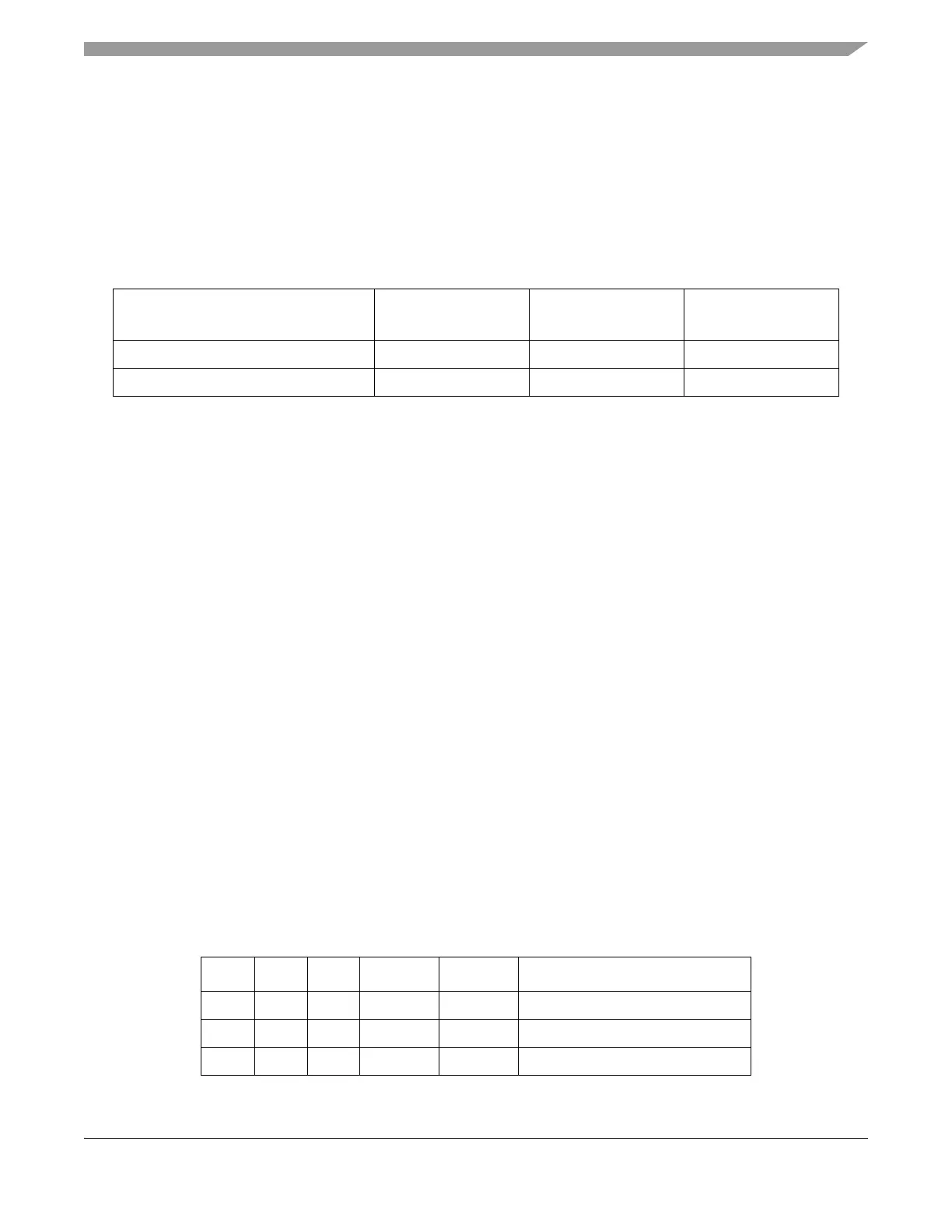
2.6.3 Recommended Pullup/pulldown Resistor Values
As the IF_SEL[1:0] signals share pins with Physical Layer Interface signals, pullup and pulldown resistors
should be used for the selection. The recommended pullup/pulldown resistor values for the IF_SEL[1:0]
inputs are given in Table 2-7:
2.7 External Host Interface
The MFR4310 can be connected through three types of bus interface (see Section 2.6.2, “External Host
Interface Selection” for information on how to select the host interface). The three types of microprocessor
interface are described below.
2.7.1 Asynchronous Memory Interface
Figure 2-5 shows how to connect the CC to a microcontroller using the AMI interface.
• Data exchange in AMI Mode is controlled by the CE#, WE# and OE# signals.
• The AMI interface is implemented as an asynchronous memory slave module, thus enabling fast
interfacing between the CC and a variety of microcontrollers.
• The AMI interface decodes its internal register addresses with the help of the chip select signal CE#
and the address lines A[12:1].
• The AMI interface accepts only aligned 16-bit read and 8-bit or 16-bit write transactions. The AMI
interface does not support 8-bit read accesses.
— The byte selects BSEL[1:0]#, the chip enable CE#, the output enable OE#, and the write enable
WE# are used to determine the type of access as shown in Table 2-8.
Table 2-7. Recommended Pullup and Pulldown Resistor Values for IF_SEL[1:0] Inputs
IO, Regulator and analog supply level
(V
DD5
)
Pullup resistor
1
1
The listed values are calculated for the MFR4310-Physical Layer connection where no internal pullup/pulldown
resistors are assumed in the Electrical PHY at the TXD_BG1 and TXD_BG2 interface lines. If an Electrical PHY
device has internal pullup/pulldown resistors connected to these signals, then the external pullup/pulldown resistor
values must be recalculated to ensure that V
IL
requirements for pulldown resistors or V
IH
requirements for pullup
resistors for the chosen V
DD5
are met. See Section A.1.9, “I/O Characteristics” for more details on V
IL
, V
IH
and V
DD5
.
Pulldown resistor
1
Units
3.3V 16 47 k
Ω
5V 10 47 kΩ
Table 2-8. AMI Access Types
CE# WE# OE# BSEL1# BSEL0# Type of Access
0 0 0 X X Illegal
0 0 1 0 0 16-bit write to word address
1
0 0 1 0 1 8-bit write to even byte address
2