Device Overview
MFR4310 Reference Manual, Rev. 2
48 Freescale Semiconductor
• WE# indicates the direction of data transfer for a transaction.
• OE# enables the AMI data output to a microcontroller during read transactions.
• INT_CC# is an interrupt line that can be used for requesting, by means of the internal interrupt
controller, a service routine from a host controller.
• The AMI interface does not support burst transactions.
NOTE
For the AMI, D0 is the LSB of the 16-bit data bus.
NOTE
If the AMI mode without the CHICLK_CC signal is selected (i.e.
IF_SEL[1:0] = 0b01), CHICLK_CC must be driven to logic 0 or logic 1 (it
must not be left floating).
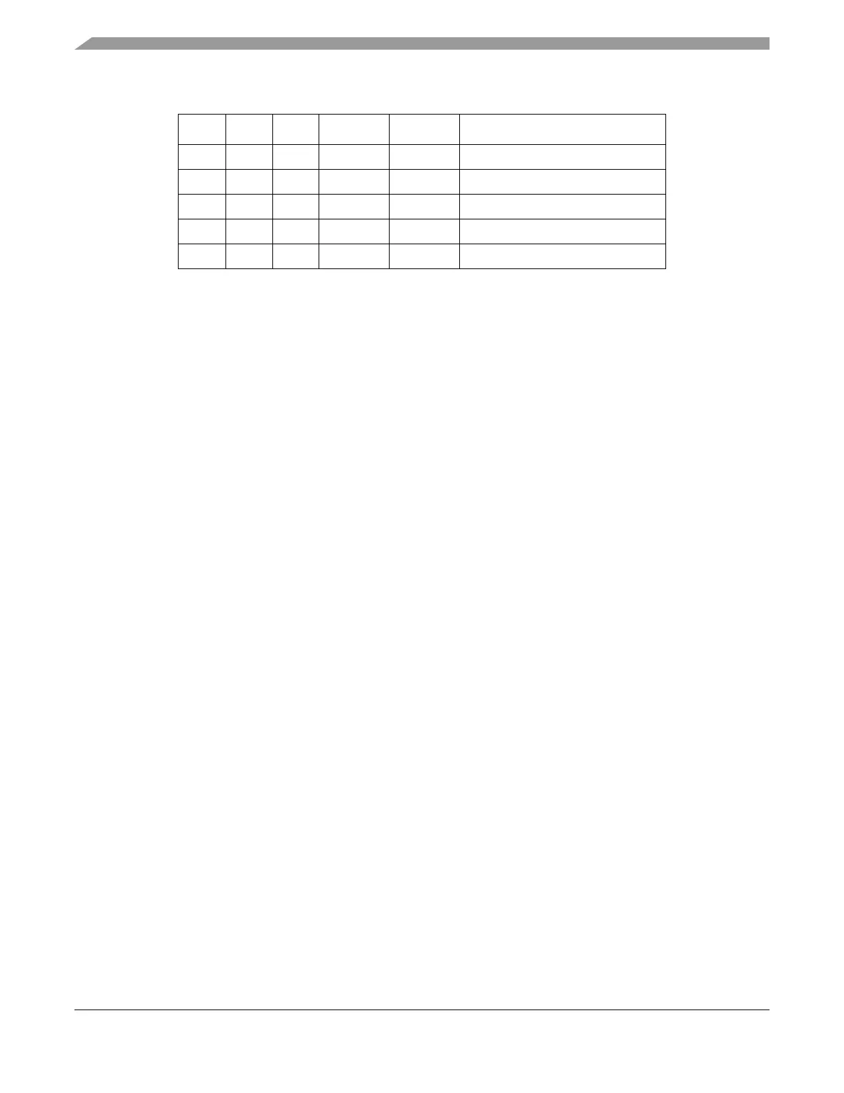
0 0 1 1 0 8-bit write to odd byte address
3
0 0 1 1 1 Illegal
0 1 1 X X no access
0 1 0 X X 16-bit read from word address
4
1 X X X X no access
1
Write data from D[15:8] to even byte address and from D[7:0] to odd byte address.
2
Write data from D[15:8].
3
Write data from D[7:0].
4
Read data from even byte address at D[15:8] and from odd byte address at D[7:0].
Table 2-8. AMI Access Types
CE# WE# OE# BSEL1# BSEL0# Type of Access