Datex-Ohmeda S/5 Anesthesia and Critical Care Monitors
4
Document no. M1125635-05
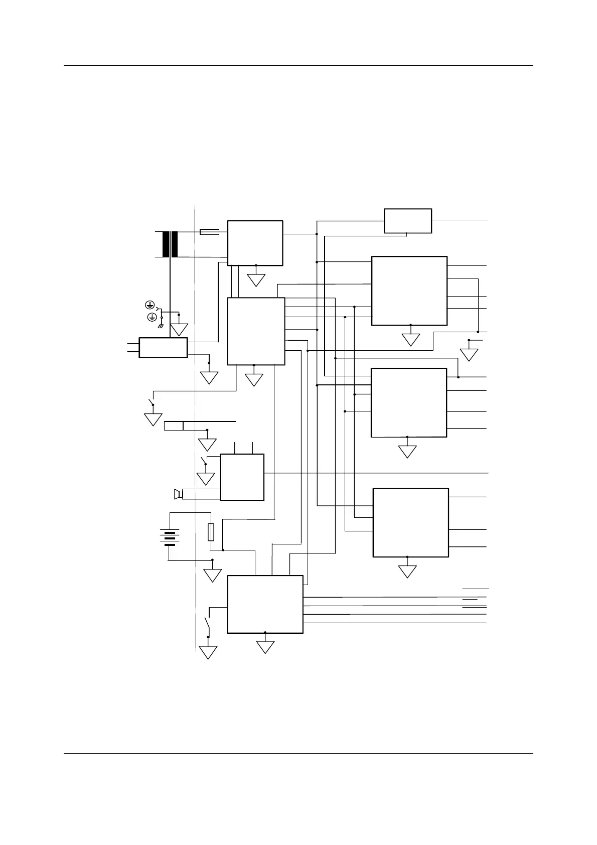
2.1.1 Power supply unit, F-CU8 Rev.12
Power supply unit contains three PC boards (power supply board, power logic board, and
Battery switch board) and four external components (mains transformer, fan, loudspeaker, and
lead acid battery).
All the operational controls in the power supply unit are located in the three PC boards.
Figure 3 Power supply unit block diagram (F-CU8, rev. 12)
-15 V
+15 V
converter
+5 V
converter
RESET
POWERFAIL
WD
+32 Vd
+15 Vd
+15 Va
+5 V
FAN
Loud-
speaker
6 V
battery
T 10 A
ON/STBY
switch on
Command
Board
AUDIOin
32 V
ON/STBY
BATCHRG
STOP
+5 Vint
GND
*CPU
INTERFACE
-15 V
converter
+32 Vd
switch
2AF
*Power
ON/STBY
control,
batchrg,
etc.
+32 Vd
*AUDIO
AMP.
15 Vd
Mains
transformer
RESET CPU
Service
reset
button
Rectifiers,
power
factor
correction
+5 Vcpu
SILENCE ALARM
Dip Switch on
Power Supply
Board
*Power ON/STBY control, AUDIO AMP.,
and CPU INTERFACE are in Power Logic Board.
All other functions are in Power Supply Board.
+5 Vcpu
pwr_supply_blck_diag_rev10.vsd
Battery
switch board
c
c
c
c
c
c
c
c
c
c
c
c
c
c
External
battery
in
24 V
+5 Vcpu
and

 Loading...


