Operation
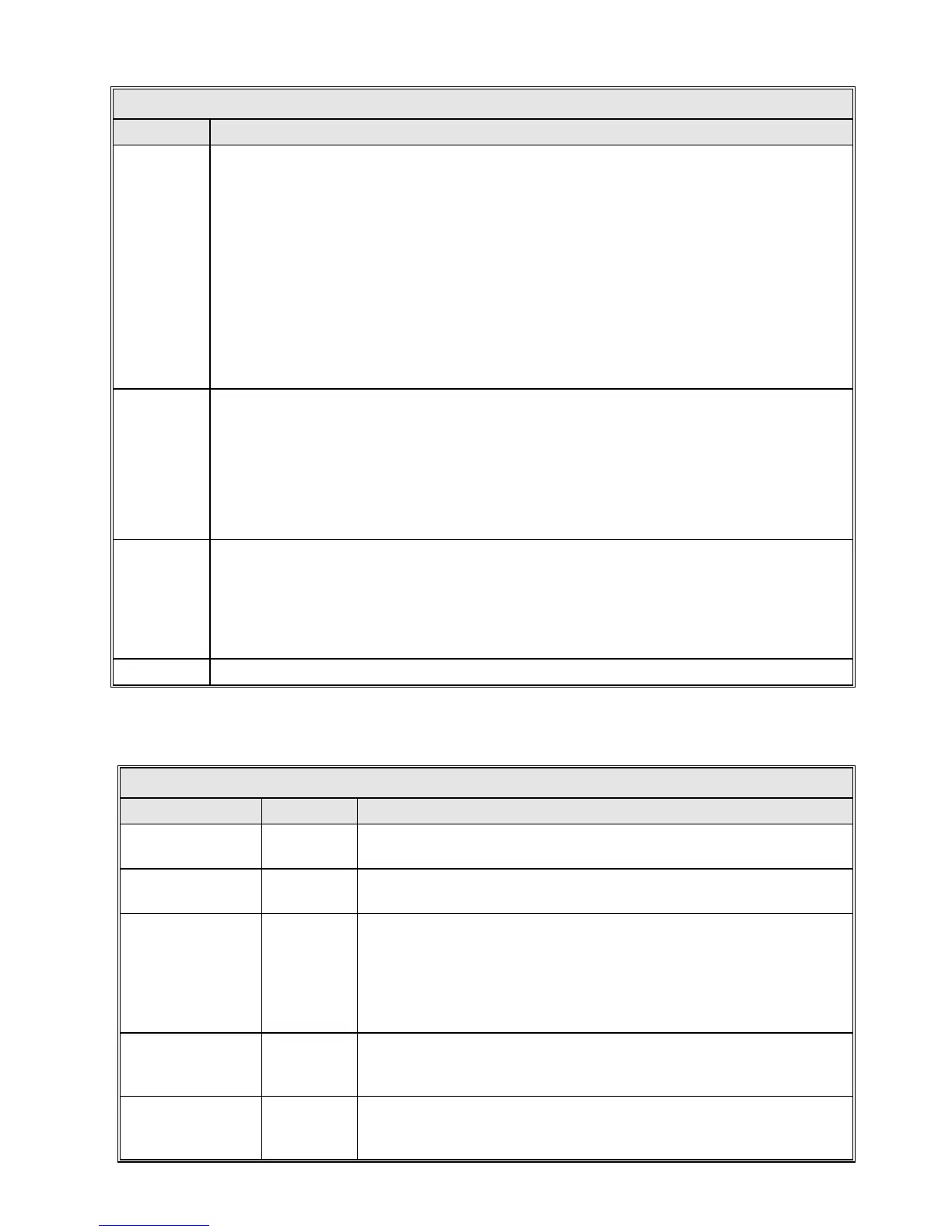
TABLE 5-8 CALIBRATE TRACKING SIGNAL
PARAMETER DESCRIPTION
Set 0 dB
point
Pressing [ENTER] on this item will cause the 0 dB point to be set at the current signal level.
The new value is displayed in "0 dB setting" below. To set this value, peak up the antenna on
all axes, adjust the signal level appropriately (see next paragraph) then press [ENTER]. This
parameter affects both the dB display on the front panel, and all tracking modes which use
tracking signal.
For "analog receivers" (that is, a tracking receiver that feeds an analog signal into the ACU's
A/D inputs,) as well as a General Dynamics TRL receiver, adjust the receiver's output voltage
to 6-8 VDC when peaked on the spacecraft. Once this is done, proceed to "Set -3 dB point."
For a DTR receiver, no change to the receiver is required. The DTR reports signal in dBm; this
setting merely offsets the receiver output such that "0 dB" on the ACU is the peak signal level.
Also, when a DTR is configured as the tracking receiver, "Set -3 dB point" and "A/D slope"
have no effect, although they are visible for backwards compatibility.
Set -3 dB
point
Pressing [ENTER] on this item will set the -3 dB point at the current signal level. Once this
step is done, and changes are saved, the tracking signal calibration is complete.
First set the 0 dB point, then run the antenna off of the target by 3 dB and press [ENTER] on
this item. This is the most accurate and preferred method. The alternative is to insert a -3 dB
attenuator at the tracking receiver input. However, this is less accurate, especially at lower
C/N values.
This has no effect when using a DTR receiver; it is included only for backwards compatibility.
0 dB setting
The "0 dB setting" value is generated b
y executing "Set 0 dB point"; the "A/D slope" is
generated by executing "Set -3 dB point". Once the 0 and -3 dB points have been computed
once for this ACU/tracking receiver combination, the "0 dB setting" and "A/D slope" should be
recorded. In the event of non-volatile RAM loss, these values may be re-entered into the ACU:
the ACU will then have the same 0 and -3 dB points as before. NOTE: A/D slope is ignored
when a DTR receiver is being used.
A/D slope NOTE: A/D slope is ignored when a DTR receiver is being used (also see 0 dB setting).
The parameters listed in Table 5-9 should only be modified by General Dynamics
personnel or experienced technicians who thoroughly understand these parameters
TABLE 5-9 OPT PARAMETERS
PARAMETER DEFAULT DESCRIPTION
Cycle time with
ST solution
00:10:00
Sets the cycle time between steptrack operations when a short-term
solution is in use.
Cycle time with LT
solution
00:20:00
Sets the cycle time between steptrack operations when a long-term
solution is in use.
Signal fluctuation
limit [dB]
0.20
This value sets the point at which steptrack, under OPT operation, will
go to a fixed scan pattern. This will only happen when an OPT model is
available and the Std. Dev. On the “OPT Statistics” screen is greater
than this parameter. A fixed scan will minimize tracking errors in a noisy
environment. The nominal value is set to 0.20 dB, but can be decreased
to cause the OPT to use a fixed pattern more frequently.
Min. ST solution
time span
1.25
Sets the minimum window of data used to create a short-
The smallest allowable value is 1.25 hours. The value may be increased
if performance of the early solutions is less than desirable.
Min. LT solution
time span
18
Sets the minimum window of data used to create a long-
The smallest allowable value is 18 hours. The value may be increased if
performance of the early solutions is less than desirable.
5-25