Overview
2.5.1.4 Drive Enable Switch
When the DRIVE ENABLE switch is in the out position, it is illuminated, and the drive
motors are enabled through the drive enable contactor. When the DRIVE ENABLE
switch is engaged, and not illuminated, the drive motors are disabled, and a message
is displayed on the screen of the 7200 ACU.
2.5.2 Drive Cabinet Controls and Indicators
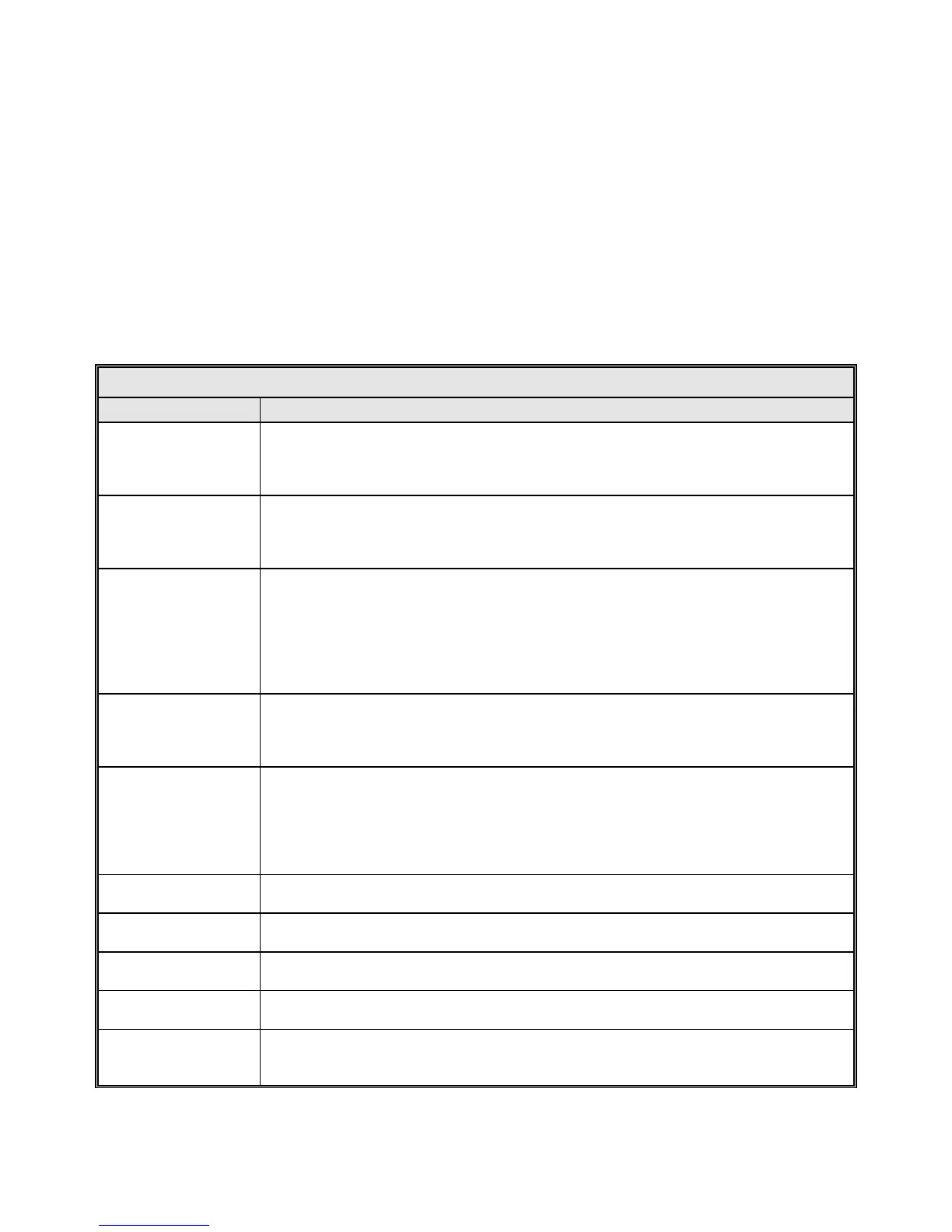
The drive cabinet contains the following controls and indicators located on the PMCU
and the Relay PCB. The function of each control is described in Table 2-10.
TABLE 2-10 DRIVE CABINET PMCU AND RELAY PCB CONTROLS
CONTROL FUNCTION
MAINT/REMOTE
The MAINT/REMOTE switch is located on the Relay PCB. When set to the REMOTE
position, transfers control to the 7200 ACU. When set to MAINT> the PMCU has control
of the system. The remote mode is selected when the switch is in the UP position.
Maintenance mode is selected when the switch is in the DOWN position.
AZIMUTH SPEED
ADJUST
Located on the PMCU. SLEW SPEED/TRACKING SPEED select switch - Selects the AZ
drive speed (functional in MAINT mode only). SLEW SPEED - This speed is programmed in
to the AZ drive and sets the AZ high-speed drive rate. TRACKING SPEED - This speed is
programmed in to the AZ drive and sets the AZ low speed drive rate.
AZIMUTH CW & CCW
SWITCH
Located on the PMCU, when this switch is turned to CW and held it rotates the Azimuth
in the CW direction at the speed determined by the AZIMUTH SPEED ADJUST Switch
until the switch is released. When the switch is released it returns to center and the
motion ceases. This switch when turned to CCW and held rotates the Azimuth in the
CCW direction at the speed determined by the AZIMUTH SPEED ADJUST Switch until
the switch is released. When released the switch returns to center and the motion
ceases.
ELEVATION SPEED
ADJUST
Located on the PMCU. SLEW SPEED/TRACKING SPEED select switch - Selects the EL
drive speed (functional in MAINT mode only). SLEW SPEED - This speed is programmed
in to the EL drive and sets the EL high-speed drive rate. TRACKING SPEED - This speed is
programmed in to the EL drive and sets the EL low speed drive rate.
ELEVATION UP & DN
SWITCH
Located on the PMCU. This switch when turned to UP and held rotates the Elevation in
the UP direction at the speed determined by the AZIMUTH SPEED ADJUST Switch until
the switch is released. When the switch is released it returns to center and the motion
ceases. This switch when turned to DN and held rotates the Elevation in the DN direction
at the speed determined by the AZIMUTH SPEED ADJUST Switch until the switch is
released. When released the switch returns to center and the motion ceases.
CONTROL POWER
CIRCUIT BREAKER
Provides circuit protection for the DC power supply tha
t provides 24 VDC for control
circuits.
CONTROL POWER
LED
The Light-Emitting Diode (LED) is located on the Relay PCB and illuminates green when
power is ON.
MAIN CIRCUIT
BREAKER
Provides circuit protection for entire drive cabinet power circuits.
DRIVE(S) CIRCUIT
BREAKER
Provides individual circuit protection for each drive.
RECEPTACLE
CIRCUIT BREAKER
(if installed)
Provides circuit protection for the duplex utility outlet on the leg of the drive cabinet.
2-25