Overview
UART), CPU interface to the Ethernet controller microcontroller, the rotary
switches S2, S3 and the dip switch S4.
3) Dependent Tests – These tests require special test jigs and are run by factory
personnel to verify operation of the system.
This self-test code is only run if DIP switch S4 pos 8 is in the ON position. To
prevent against “accidentally” running these tests, the tests are also interlocked
with the Keyboard controller card. If the keyboard controller card is detected, the
tests will be aborted. The serial port between the keyboard controller card and the
display controller card should be unplugged to allow the tests to proceed.
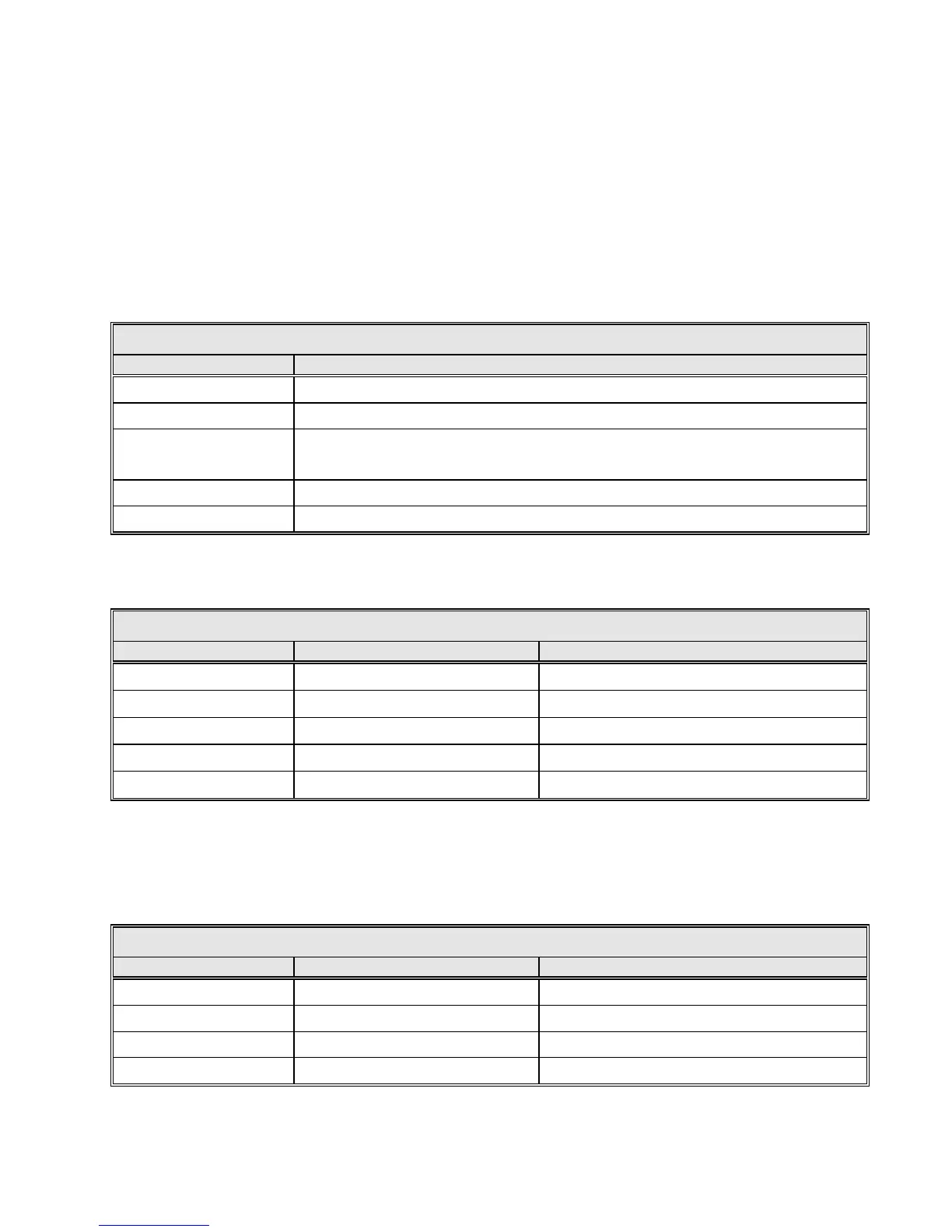
TABLE 2-3 VCPU S3 HEX ROTARY SWITCH POSITIONS DEFINITION
0 (Factory Setting) On power-up, no self-test code is run.
1 On power-up, the destructive suite of tests is run.
2
On power-up, the independent suite of tests is run.
3
On power-up, the dependant suite of tests is run.
4 - E Unused.
F On power-up, run all tests sequentially.
DIP Switch S6 – This DIP switch directly controls various hardware related board
functions as defined in the following table:
TABLE 2-4 VCPU S6 DIP SWITCH POSITIONS DEFINITION
OFF POSITION (SWITCH OPEN)
ON POSITION (SWITCH CLOSED)
1 - 4
Flash Write Disabled ♦♥
Flash Write Enabled
5
EEPROM Write Disabled♦
6
Normal Operation♦
Hold the VCPU board in Reset
7
CPU Watchdog Disable♦
CPU Watchdog Enable
8 Board Reset Disabled
Board Reset Enabled♦
♦ Denotes the normal operating position of the switch (factory setting).
♥To program the flash boot banks with new application code, S6 pos 1-4 must be in the ON position; after programming is
complete, return these four switches to the OFF position.
DIP Switch S4 – This DIP switch controls various software functions as defined in
the following table.
TABLE 2-5 VCPU S4 DIP SWITCH POSITIONS DEFINITION
OFF POSITION (SWITCH OPEN)
ON POSITION (SWITCH CLOSED)
1 Password Protection Enabled♦ Password Protection Disabled
2-6 Unused♦
7 Standard Boot Up ♦
Resets all params to factory defaults on Boot
8 Self Test Mode Disabled♦ Self Test Mode Enabled♠
♦ Denotes the normal operating position of the switch (factory setting).
♠ Enabling self-test mode should ONLY be performed when directed to do so by General Dynamics technical support. Some
of the self-tests erase NVRAM (parameter storage space) and some erase all the flash banks (application firmware).
2-11