Installation
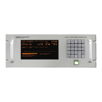
4.3.4.3.2 PMCU Display Setup
In order for the PMCU display to operate, the serial link connections must be in place
between the ACU and drive cabinet, and the EIA/TIA422 (J16 or Port 3) serial port
must be setup properly in the ACU. Failure to perform the following steps will result
in a LINK LOSS fault on the PMCU display. The PMCU will still be able to control the
antenna locally.
1. Complete the serial link connections between J16 (EIA/TIA422) on the ACU and
TB1 in the drive cabinet. Refer to Table 4-4B for connection description. Refer to
Table 4-12 for a complete EIA/TIA422 pin-out of port J16.
2. From the 7200 ACU Main Menu, select Edit System Configuration…, Remote Port
Configuration. Setup the following parameters. Please be aware that these port
configuration changes must be saved before the new settings become valid.
4.3.5 Resolver and Encoder Connections
Single-speed, size-11 resolvers are standard for azimuth, elevation, polarization,
and 4
th
axis (optional). Two-speed (size-20 resolvers) and optical encoders are
options available for azimuth and elevation.
4.3.5.1 Resolver Connections
The connections for size-11 resolvers are provided in Table 4-6A. Connect each
connector to the appropriate connector on the rear of the ACU. J6 & J5 are 9-pin
D connectors, and J7 and J8 are 25-pin D connectors. Refer to Figure 4-4 for
location of the connectors on the ACU. See Appendix H for using CTB055 to
attach the resolver wires to the resolver control cable.
NOTE: Connect shield leads at the ACU connector end only. Do not allow the shield
leads to come into contact with one another or with the resolver case. At the antenna
end, tape each lead separately. Connecting shields at both ends creates a current path
(ground loop) which may cause erratic position readings.
TABLE 4-6A RESOLVER CONNECTIONS—SINGLE SPEED, SIZE-11
7200 – J6, J7, J8, J5 FUNCTION* RESOLVER LEAD COLOR
2 R1 Red/White
8 R2 Yellow/White
9 S1 Red
5 S2 Yellow
4 S3 Black
3 S4 Blue
1,6,7 Shield Not Connected at Resolver
4-11

 Loading...