Installation
TABLE 4-14 COMMUNICATION PORT CONNECTIONS (EIA/TIA-
422B)
J18, J19, J20 DESIG FUNCTION
1 XDATA+ Transmit (+) *
2,3 NC No Connect
4 RDATA+ Receive (+) *
5 GND Shield (Chassis Gnd)
6 XDATA- Transmit (-) *
7,8 NC No Connect
9 RDATA- Receive (-) *
* Standard connection scheme for EIA/TIA-422B port.
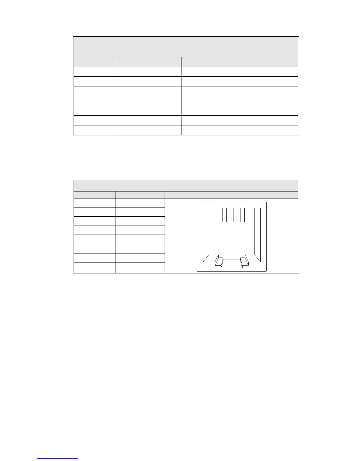
The Ethernet port, J9, is available for use with an M&C system. The pin
connections are detailed in Table 4-15.
TABLE 4-15 10BASE-T ETHERNET CONNECTIONS (IEEE 802.3)
1 TX+
1 2 3 4
5 6 7
8
2 TX-
3 RX+
4 NC
5 NC
6 RX-
7 NC
8 NC
4.3.9 Remote Beacon Select and Summary Fault Connections
TB1 on the 7200 ACU rear panel provides a summary fault output (normally closed
dry contacts) and four contact closures for remote beacon selection. The fault
contacts have continuity between them under normal conditions but provide an
open circuit under fault conditions. The terminals for remote beacon select are
open circuits for the respective beacon 1 through 4 unless that beacon is selected
through the 7200 ACU front panel. Thus, the customer interface beacon contacts
for any selected beacon provide a closed circuit, allowing the flexibility of
switching beacon channels and/or sources on compatible equipment. The
remaining IN and OUT terminals are reserved for future use.
Refer to Table 4-16 and make the appropriate connections to TB1 on the 7200
ACU rear panel.
4-20