Overview
2.5.1.2 The Alphanumeric Display
The 7200 ACU user interface combines an 8-inch by 4-inch electroluminescent
display with a custom 24-station keypad to provide the most straightforward,
powerful, and user-friendly operating platform in the industry. Figure 2-8 shows
each section of the 7200 ACU display, and each section is described in detail in
the following sections.
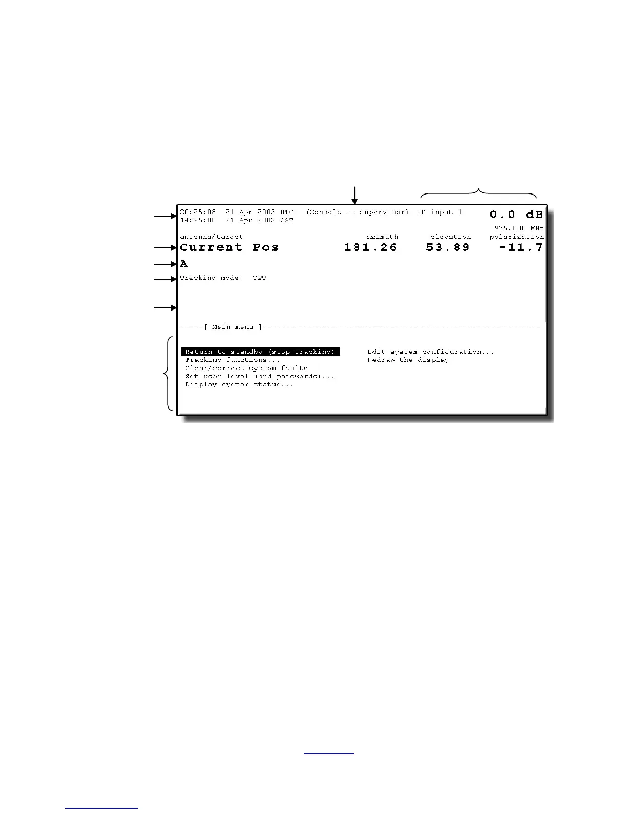
Figure 2-9 7200 Antenna Control Unit Display
The display is divided into upper and lower sections: the upper section (approximately
60 percent) is dedicated to real-time information display, and the lower section is
used for interactive mode selection, configuration, editing, and help messages. In the
real-time display section, "current pos" AZ and EL angles are displayed in double-size
characters. A user-configurable alphanumeric field to the left of the current position
angles allows for labeling (naming) the display, primarily to aid identification in
multiple-antenna stations. The line of information directly below the current position
information (also double-size characters) identifies the target currently being accessed
by the system. If the system is in the process of moving from one target to another,
or in a program tracking mode of operation, the target (or next position) angles are
also displayed directly below the current position angles.
Immediately below the target name field is a line of information that displays the
current mode of operation and pending modes. The current target shown in Figure 2-
9 is “A” and the mode status line shows that the current tracking mode is OPT.
Shown at the top of the display are current time (Coordinated Universal Time (UTC)
and/or local), user level (Monitor, Operator, or Supervisor) and tracking signal source
and level. Each of these items may be blanked out by the user if not required in a
particular application (refer to Section 5.8.6.14 for information on user interface
options).
Configuration
Editing
Help Messages
Current Position
Tracking Signal
Status & Level
2-22