Installation
If 4-axis system, perform steps 1-13.
6. Connect the wire from terminal 1 of the POL motor to the TB1 terminal labeled
POL CW in the drive cabinet.
7. Connect the wire from terminal 3 of the POL motor to the TB1 terminal labeled
POL CCW in the drive cabinet.
8. Connect the wire from terminal 2 of POL motor to TB1 terminal labeled N.
9. Connect the POL AXIS motor case ground to the ground terminal on TB1 in the
drive cabinet.
10. Connect the wire from terminal 1 of the 4TH AXIS motor to the TB1 terminal
labeled POL CW in the drive cabinet.
11. Connect the wire from terminal 3 of the 4TH AXIS motor to the TB1 terminal
labeled POL CCW in the drive cabinet.
12. Connect the wire from terminal 2 of 4TH AXIS motor to TB1 terminal labeled
N.
13. Connect the 4TH AXIS motor case ground to the ground terminal on TB1 in
the drive cabinet.
4.3.3 Limit Switch Connections
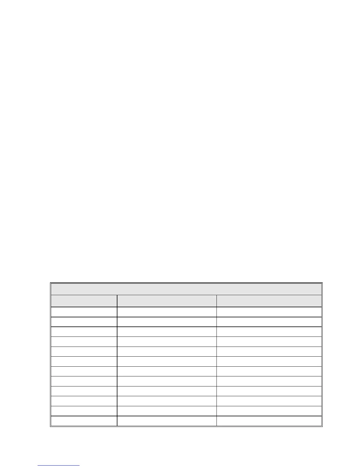
Connect the limit switches to TB1-1 through TB1-9 on the drive cabinet as shown
in Table 4-2. Note that normally closed (open upon limit) contacts are required.
TABLE 4-2 LIMIT SWITCH CONNECTIONS TO THE DRIVE CABINET
DRIVE CABINET TB1 DEVICE FUNCTION
1 Az Limit Switch Az CW Limit
2 Az Limit Switch Az Limit Common
3 Az Limit Switch Az CCW Limit
4 EL Limit Switch EL Up Limit
5 EL Limit Switch EL Limit Common
6 EL Limit Switch EL Down Limit
7 POL Limit Switch POL CW Limit
8 POL Limit Switch POL Limit Common
9 POL Limit Switch POL CCW Limit
10 4TH AXIS Limit Switch 4TH AXIS CW Limit
11 4TH AXIS Limit Switch 4TH AXIS Limit Common
12 4TH AXIS Limit Switch 4TH AXIS CCW Limit
4-7