Operation
5.8.6.10 RF/Geometry...
The RF/Geometry... enables/disables POL control and contains the parameters
described in Table 5-35. If POL is controlled by the ACU, set this parameter to
enabled. If this parameter is disabled (for 2-axis systems), POL will not appear on
the real-time display or in any menus.
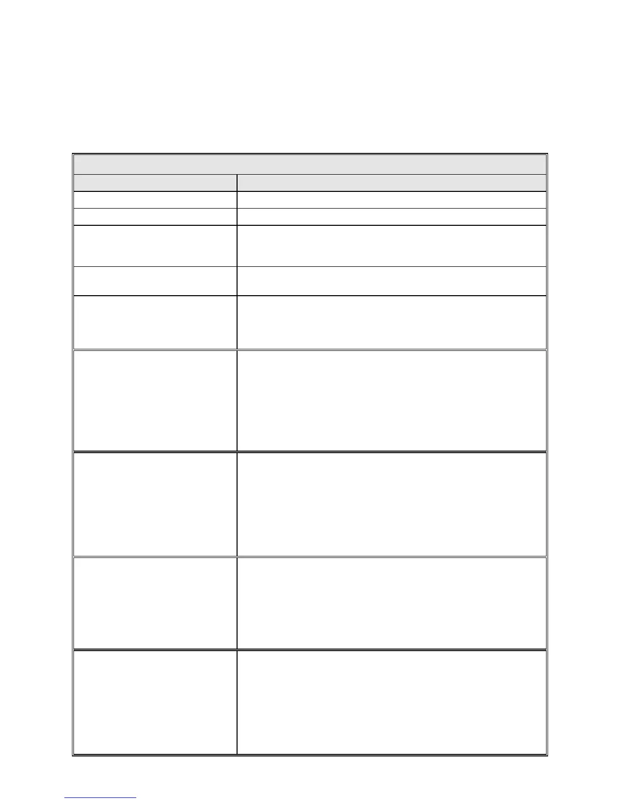
TABLE 5-35 RF/GEOMETRY PARAMETERS
PARAMETER DESCRIPTION
Polarization axis Set this to Enabled if the POL axis is controlled by the ACU.
Antenna droop correction Set this to Enabled if the POL axis is controlled by the ACU.
Amplitude droop corr. [deg]
The amplitude of the droop correction is used to adjust the EL look
angle for mechanical droop. This value is determined from structural
analysis of the dish.
Elevation alignment [deg]
The EL alignment angle is the EL angle at which the dish was
balanced and focused. This value is used in the droop correction.
XEL correction
This parameter enables software correction of xel error. That is the
elevation axis is moving orthogonal to azimuth but the RF beam is
tilted creating a xel error. If DISABLED the correction is not used.
This correction can be used independent of Droop correction.
AZ ratio correction
This parameter enables software correction of azimuth ratio error.
That is if the azimuth encoder is not exactly o
n a 1:1 axis with the
azimuth rotation. This is a linear correction only and is intended for
fine tuning. The correction is calculated by multiplying the delta of
current reading minus the offset set point times this parameter
divided by 180.000 and then
added back to the current reading. If
DISABLED the correction is not used. This correction can be used
independent of Droop correction but not with XEL correction.
EL ratio correction
This parameter enables software correction of elevation ratio
error. That is if the elevation encoder is not exactly on a 1:1 axis
with the elevation rotation. This is a linear correction only and is
intended for fine tuning. The correction is calculated by
multiplying the delta of current reading minus the offset set point
times this parameter divided by 180.000 and then added back to
the current reading. If DISABLED the correction is not used. This
correction can NOT be used simultaneously with Droop correction
POL ratio correction
This parameter enables software correction of polarization ratio
error. That is if the polarization resolver angle is not exactly on a
1:1 movement with the RF axis. This is a linear correction only.
The correction is calculated by multiplying the delta of current
reading minus the offset set point times this parameter divided by
10.000 and then added back to current reading. If DISABLED the
correction is not used.
Fixed CP angle
This parameter enables the use of a predefined polarization angle
when ever circular mode (CP) is in use. The polarization angle set
here will override any polarization angles set in the targets for a
tracking mode. This only operates when the feed has CP/LP
switching and a feed alignment angle (pol) is enabled. When in
linear operation the polarization angle defined in the target has
priority. If DISABLED the pol angle in the target will be used to
set pol for both CP and LP operation.
5-67