Installation
4.3.4 Installing the 7200 ACU Control Cable
The procedures for installing the 7200 ACU control cable are different for the
standard product and a system with the optional low-temperature package. For
standard system installation, refer to Section 4.3.4.1; for systems with EIA/TIA-
422B cable installation refer to Section 4.3.4.2.
4.3.4.1 Standard System 7200 ACU Control Cable Installation
1. Connect one end of the 25-conductor control cable (Belden 8459 or equivalent)
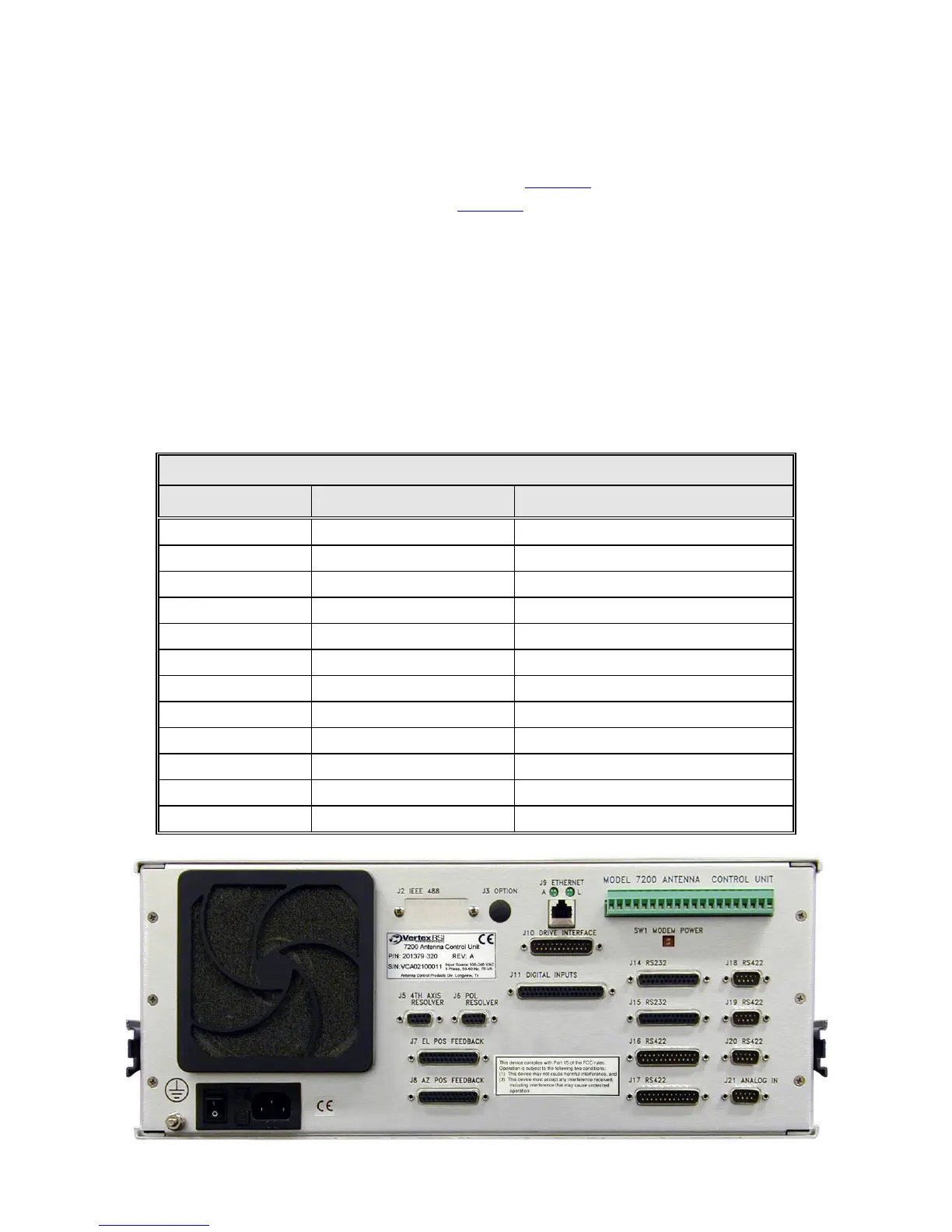
to the 25-pin connector labeled DRIVE INTERFACE (J10) on the back of the
7200 ACU (refer to Figure 4-4). Refer to Table 4-4A for a pin-out and the
function of each conductor.
2. Connect the other end of the 25-conductor cable to J1 on the relay board inside
the drive cabinet (refer to Table 4-4A).
TABLE 4-3 REAR PANEL CONNECTORS
REF DESIG TYPE GENDER
J2 (Optional) 24-pin IEEE-488 SOCKET (female)
J3 (Optional) BNC SOCKET
J5, J6 DB-9 SOCKET
J7, J8 DB-25 SOCKET
J9 RJ-45 SOCKET
J10 DB-25 PLUG
J11 DB-37 SOCKET
J14, J15 DB-25 SOCKET
J16, J17 DB-25 PLUG
J18, J19, J20 DB-9 PLUG
J21 DB-9 PLUG
TB1 20 PIN PLUGGABLE TERMINAL STRIP
Figure 4-4 7200 Antenna Control Unit Rear Panel
4-8