Installation
The connections for two-speed, size-20 resolvers are provided in Table 4-6B.
Connect each connector to the appropriate connector on the rear of the ACU. J7
and J8 are 25-pin D connectors. Refer to Figure 4-4 for location of the connectors
on the ACU.
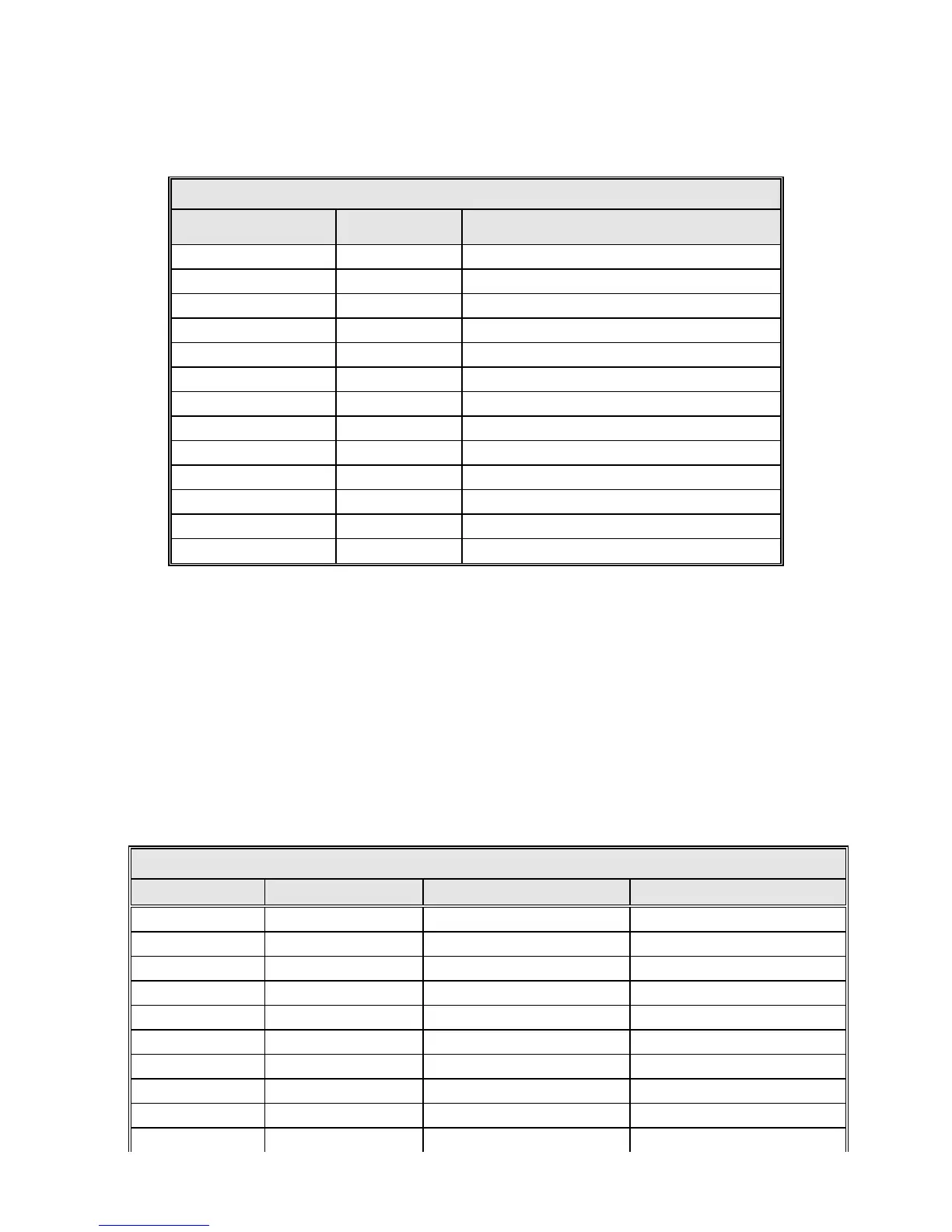
TABLE 4-6B RESOLVER CONNECTIONS—TWO-SPEED, SIZE-20
7200 –J7, J8 FUNCTION*
RESOLVER PIGTAIL LEAD COLOR AND
CIRCULAR CONNECTOR PIN NUMBER
2 R1 Red/White 6
8 R2 Black/White 7
9 S1 Red 1
5 S2 Yellow 4
4 S3 Black 2
3 S4 Blue 5
10 S11 Red/Green 8
13 S12 Yellow/Green 11
11 S13 Black/Green 9
14 S14 Blue/Green 12
1,6,7,12,15 Shield Not Connected at Resolver
No Connection Reserved 3
No Connection Reserved 10
* Shielding pairs: R1-R2, S1-S3, S2-S4, S11-S13, S12-S14.
If position readouts bobble or do not track to antenna motion, refer to Section 5.0
in Appendix E, Troubleshooting Guide, of this manual.
4.3.5.2 Optical Encoder Connections
This section applies only if optical encoders are used for the azimuth and elevation
transducers. Model 800499-01 is the optical encoder J-box assembly. Model
800499-02 is the assembly with optional Position Display Unit (PDU), which
shows position feedback even without an ACU. 18-bit encoders connect directly
to the ACU and do not use a J-box. See Table 4-8C.
TABLE 4-7 OPTICAL ENCODER CONNECTIONS
7200 – J7, J8 FUNCTION 800499-02 800499-01
15 CLK 1 1
16 CLKN 2 2
17 SHLD (CLK) NC NC
18 CLK2 7 NC
19 CLK2N 8 NC
20 SHLD (CLK2) 10 NC
21 DAT 3 3
22 DATN 4 4
23 SHLD (DAT) 9 NC
24 +24V 5 5
4-13