Overview
2.4.1.1 VertexRSI Central Processing Unit (VCPU) PCB Assembly
The 7200 ACU uses the Motorola 68030 32-bit microprocessor as the Central
Processing Unit (CPU), providing sufficient computing power for the sophisticated
control and tracking algorithms used by the ACU. A dedicated VME CPU circuit
card is provided, which includes the CPU, Read-Only Memory (ROM), Random
Access Memory (RAM), bus control circuitry, and nonvolatile memory control
circuitry, providing efficient and reliable system operation.
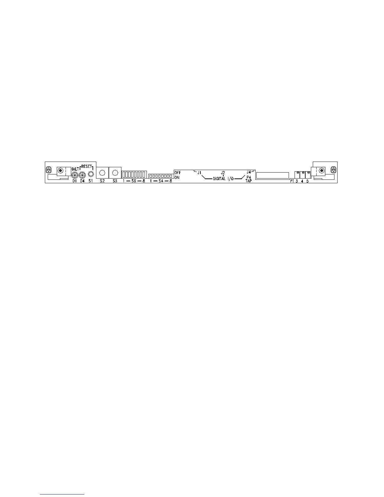
The VCPU card has several indicators and switches mounted on the VME front
panel to provide the user with basic diagnostic information.
Figure 2-6 VCPU Card
D1 Halt LED – This bi-color green/red LED indicates the operational status of the
68030 CPU. If this LED is red the processor is halted and the system will not
operate, consult the factory for assistance. This LED will always be illuminated
green even when the board is held in reset.
D4 Reset LED – This bi-color green/red LED indicates the reset status of the board.
If this LED is red it means the board is in reset. The following events can cause a
reset condition to occur:
1) 2.5 VDC undervoltage fault – If this is the cause then LED D2 (SMT LED
located between the battery and the left hand side of the board) will be
extinguished indicating that the 2.5V power supply source has fallen below
2.38VDC. Check the voltage to ensure it is above 2.38VDC. Potentiometer PT1
sets the threshold for this fault (Re-adjust per General Dynamics document CG-
0283).
2) 3.3 VDC undervoltage fault – If this is the cause the battery monitor IC (U1)
has detected a voltage lower than 2.9 VDC. Check the 3.3V regulator output
(VR1) to see if 3.3V is the output voltage.
3) 5.0 VDC undervoltage fault – If this is the cause then LED D3 (SMT LED
located between the battery and the left hand side of the board) will be
extinguished indicating that the 5.0V power supply source has fallen below
4.75VDC. Check the voltage to ensure it is above 4.75VDC. Potentiometer
PT2 sets the threshold for this fault (Re-adjust per General Dynamics document
CG-0283).
4) Dip Switch S6 pos 6 in the ON position – Leaving this dip switch in the ON
position holds the board in reset; change the position of the switch to the OFF
position to allow the board to operate normally.
2-9