Appendix J
FIELD PROCEDURE(s) TO INSTALL CTB055
STANDARD METHOD
1. Strip the insulation from the Resolver wire (Approx 3/8”)
2. Strip the insulation from the connecting cable (Approx 2/8”)
3. Twist the two wires tightly together
4. Solder the two wires
5. Cut the exposed twisted wires to a final length of about ¼”
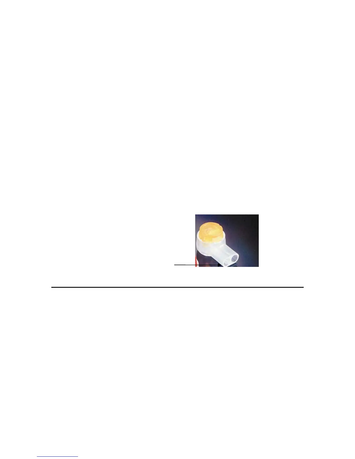
6. Insert the two wires into one side of the CTB055.
7. Crimp using the approved 3M crimping tool (Part # E9-BM).
Insert solders wires in to one side only
ALTERNATE METHOD IF CTB055 IS NOT AVAILABLE
1. Strip the insulation from the Resolver wire (Approx 3/8”)
2. Strip the insulation from the connecting cable (Approx 2/8”)
3. Slip some appropriately sized heat shrink over one of the wires
4. Twist the two wires tightly together
5. Solder the two wires
6. Position the heat shrink over the exposed soldered wires